PLEASE NOTE: If you had an account with the previous forum, it has been ported to the new Genetry website!
You will need to reset the password to access the new forum. Click Log In → Forgot Password → enter your username or forum email address → click Email Reset Link.
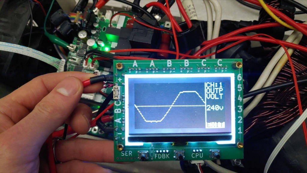
The skeptic in me cringes at the thought of trusting the on-board scope. He says "Lies! All lies!" But yes, the diagnostic scope screen shows a pretty clean wave through the entire load range. "Perfect... too perfect... ..."
Haha, hehe. Of course I understand...any chintzy Chinese inverter would be liable to just display a perfect sine regardless of the output. I seem to recall hearing/seeing something of that sort on a YT video....where what the screen showed was anything but what the output actually was!
But I can assure you that the 'scope on the GS inverter is real, it's not faked. If the output is not a sine wave, you'll see it--albeit limited by the low resolution of the screen.
Lemme see...I should be able to show you a flat-topped sine wave on the GS 'scope pretty easily here....
One caveat: any GS inverter with an A.1 / B control board WILL show a rather messed-up AC waveform, but this is NOT what's actually on the output! That's actually the result of what I thought was clever to use optoisolators to electrically isolate an analog waveform. Great on paper--and pretty poor in real life! All Rev. C boards use signal transformers for isolation, providing a much more accurate picture to the CPU of the actual waveforms!
I'll get my bench inverter going here, and show a really flat-topped waveform on the 'scope. Pretty easy with my bench supply: I'll just turn the input voltage down way below the "pure sine minimum" and it'll flat-top. The difference here being that the GS inverter transformers' ratio is a lot steeper than a PJ, so there's more headroom--and as a result, it's far less likely to flat-top ("saturate").
40vDC input, no load. There 'ya go! I made sure to include the Rev. C board in the background 😉.
Quick question as i am in a bit of doubt suddenly, is it ok to bond both N1 and N2 together to service the off grid house with one common Neutral or should I keep both Neutrals separate? Maybe was answered somewhere on the forum but cant seem to find answer and don't want to see magic smoke in the battery room... ^^
Quick question as i am in a bit of doubt suddenly, is it ok to bond both N1 and N2 together to service the off grid house with one common Neutral or should I keep both Neutrals separate? Maybe was answered somewhere on the forum but cant seem to find answer and don't want to see magic smoke in the battery room... ^^
We don't have any clear pictures of the inverter and/or how the boxes are currently wired together.
My guess is that this is an "AMG"-style inverter, where you can wire the output for either 120v single phase OR 240v split-phase. And whether you can wire both "N" terminals together depends on which output type you'd like.
My guess is that this is an "AMG"-style inverter, where you can wire the output for either 120v single phase OR 240v split-phase. And whether you can wire both "N" terminals together depends on which output type you'd like.
The picture show the back side of the new design 20000 watts 2 boxes Powerjack . From the front Option B is the safe way to bond the N1 and N2 togetrer . Option A is for two separate 120vac .
.png.aba51d98c3f8d4c33e929d46c63c80e5.png)
.png.51540e858f509af33495b728ffcae535.png)
23 minutes ago, Sid Genetry Solar said:We don't have any clear pictures of the inverter and/or how the boxes are currently wired together.
My guess is that this is an "AMG"-style inverter, where you can wire the output for either 120v single phase OR 240v split-phase. And whether you can wire both "N" terminals together depends on which output type you'd like.
Yes, i have it connected as AMG style for two 120V outputs, ... thank you dickinson i almost tried to bond them without verifying...
//content.invisioncic.com/g308908/monthly_2023_01/1005903995_WhatsAppImage2023-01-05at3_30_08AM.jpeg.ea1cb975ddc8fc3a157603feaa5de036.jpeg
//content.invisioncic.com/g308908/monthly_2023_01/723299045_WhatsAppImage2023-01-05at3_54_46AM.jpeg.cbcc7639bca1ee6b118f22d87b79fceb.jpeg
DO NOT bond the 2 neutrals N1 N2 . Option A is for 2 separate 120 vac . The back side is wired correctly . UPOWER done something right finally .

the separate boxes is a definite plus for working inside, although they take up more space,,, not really a problem most of the time...
it looks like the stainless steel protective covers now have a better fit,,,,they are basically to protect it during shipping anyways and do protect it a lot as the shipping companies routinely drop heavy things....
PowerJack manufactures the Upower inverters... at the PowerJack manufacturing plant...
do not be afraid to remove the top covers....to take a look inside.....i have done this many times....there is no problem but always be careful when it is connected....best to check it all out before you connect to the battery.\
I never connect any inverter to the grid as I do all off-grid....
all my LiFePO4 battery charging is done via the PV solar panels in my off-grid builds...
Quick update, the inverter almost melted at the post where transformer connects to control module at just 2KW for few hours... The nut seems to be made from regular steel...Another problem that does not help is that they reduced from four connector to just two...
The manual suggest just put the lug behind the steel washer and bolt it down, so over 400 Amps going throught steel nuts and steel washer, disaster waiting to happen...
I ordered some aluminium M10 nuts to try to replace the steel nuts... at least the rod seems to be made from aluminum...
Anybody have a better solution?


.jpeg.36b4b02a5e6a8f7f5fc757d09ededfd6.jpeg)
.jpeg.21208de9a4668837c7a9fe82c40d1699.jpeg)
The manual suggest just put the lug behind the steel washer and bolt it down
The stud should have washer and then tighten the first nut and then your wire and then tighten the outer nut . You have the waher and then the wire and then double 2 outer nuts so the stud is not tight . The inner nut keep the stud tight and the outer nut keep the wire tight . The DC 48 v input wiring on the left is correct .
The DC 48 input is NOT correct and need the stud tighten with the inner nut also .
<a contenteditable="false" data-ipshover="" data-ipshover-target="/profile/206-jon-snow/?do=hovercard" data-mentionid="206" href="/profile/206-jon-snow/" rel="">@jon snowQuite an impressive capture there of a glowing hot connection! And at only 2kw??? Seriously, that's terrible!
Apart from re-engineering the connections, there's not too much you can do. You can try aluminum nuts, but I'm not sure how much that would improve things--especially if there's a washer in the picture too.
The manual suggest just put the lug behind the steel washer and bolt it down
Yes, I have done per your suggestion and will be testing it again soon ... will keep you posted...
@jon-snowQuite an impressive capture there of a glowing hot connection! And at only 2kw??? Seriously, that's terrible!
I am thinking the aluminium nut will pose a smaller resistance and pass the current via the post via the aluminium thread surface... if that doesnt work then will have to improvise some more...
New issue... Just opened the lid to inspect the inverter for internal damage after meltdown... noticed that this there was this loose cable in the first picture ... does anyone know where it should be connected?

.jpeg.9db033e3e6c15f4b682936bb0457a1fe.jpeg)


.jpeg.83906571ed971c5c39bb3cffbd7aebcc.jpeg)


.jpeg.2b710e3d64ceabd16677723648196ac5.jpeg)

