PLEASE NOTE: If you had an account with the previous forum, it has been ported to the new Genetry website!
You will need to reset the password to access the new forum. Click Log In → Forgot Password → enter your username or forum email address → click Email Reset Link.
Hello everyone,
I'm looking for some guidance regarding my 48V split (110/220ac) U-Power 15k inverter. Recently I had to replace all the mosfets boards and the driver. The inverter was able to power a fridge for two days with no issue but then it started to overload (red LED) and alarm. Now when I try to power a light bulb it lights up for a few seconds and then it turns off. I also noticed that only the mosboards and the driver LEDs are turning on green. I don't understand how the inverter drives and lights up a lamp bulb for a few seconds with most of the green status LEDs being off.
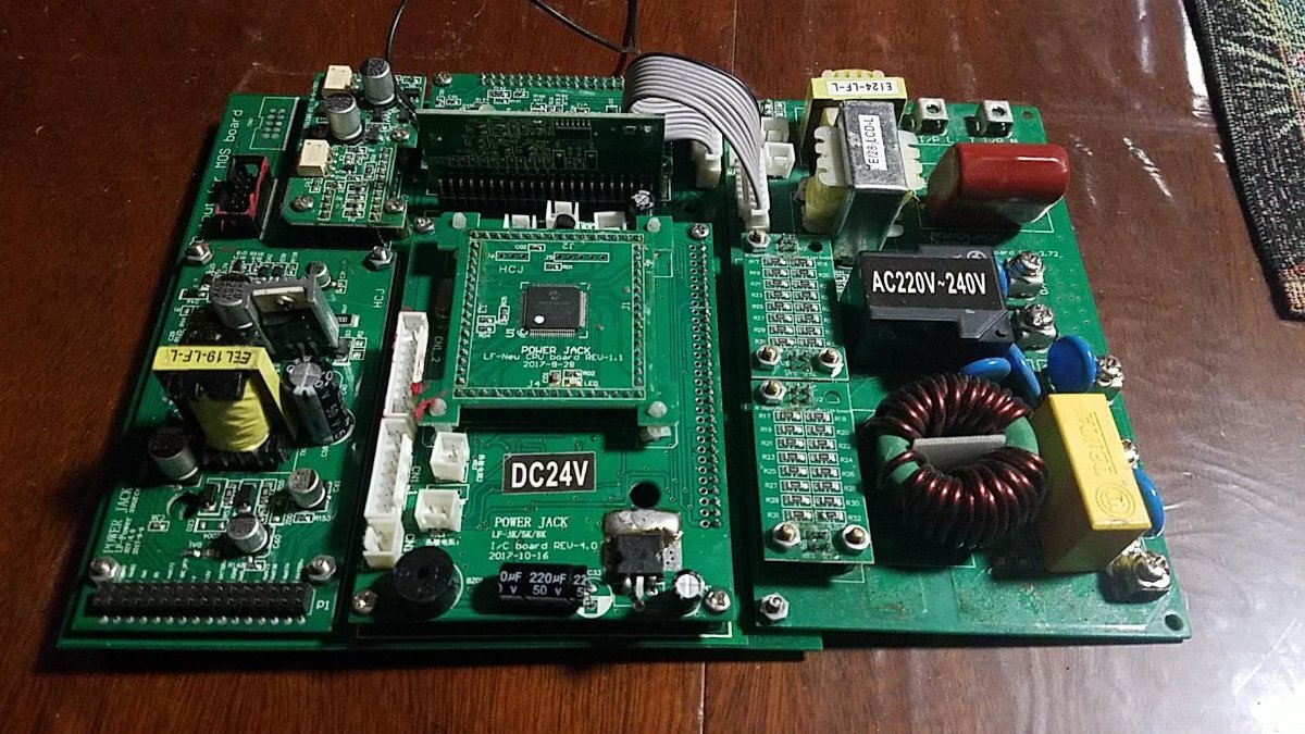
This inverter came with the following board dates and revisions:
LF Power source board = 2017-9-9 Rev 4.0 (LED blinks)
LF Neu CPU board = 2017-9-28 Rev 1.1 (LED off)
LF-overload protection board = 2017-3-27 Rev 3.71 (LED off)
LF-3K/5K/8K signal board = 2017-5-3 Rev 3.72 (LED off)
LF-3K/5K/8K I/C board = 2017-5-3 Rev 3.72 (LED off)
LF-3K/5K/8K AC Charger board = 2017-8-30 Rev 3.72 (LED off)
LF-Driver = 2017-9-9 Rev 4.0 (new and LED on)
LF 3K_MOSBoard = 2014/10/27 Version 2.2 (4 new an all LED on)
LF-3K_MainBoard = 2016/5/4 Version 2.6 DRV2/GO2
What recommendations you can share with me to fix this issue? Are replacement parts still available like to replace the boards specially the power source board or any other that could cause these symptoms?
Best Regards,
Miguel
email=sanchez00081@hotmail.com
Now when I try to power a light bulb it lights up for a few seconds and then it turns off.
When the inverter shuts off after the few seconds, does it turn on the red LED and beep?
If you could upload a short video to YT of what the inverter does, that'd be helpful.
If you have a DC clamp meter, that also would be very helpful.
Thank you for your quick response.
I reseated all the inverter cards and connections. The cables were routed away from the transformer to minimize cross talk. A lamp was used to provide a small load. I powered up the inverter and just the green INV ON indicator turn on. No alarm came up this time and the lamp load turned on. The inverter is now working normally (no alarm and no longer shutting off). I used my multimeter to measure L1-N = 94.7 vac and L2-N = 103.9 vac. Also the battery was measured at around 52Vdc during today's test.
This inverter has never output the full 110/220vac since brand new. I also noticed for a long time that the board's green LEDs have been off while the inverter was being used for many months (except for the mosboards and the driver that their LEDs turn on as expected). The other top boards LED does not seem to be working and looks like they're not a good indicator for issues.
Is there a way to get a higher L1 and L2 vac closer to 110 by increasing the battery voltage or some other way? I know the battery voltage should not go higher than 55Vdc or it could cause problems. Is there any other recommendations?
Thank you for your quick response.
Is there a way to get a higher L1 and L2 vac closer to 110 by increasing the battery voltage or some other way?
Hard to say; technically, what's responsible for regulating the output voltage is the CPU and associated feedback circuitry. Does your inverter have any little knobs on the front panel at all? If not, you probably will have to do some SMD soldering to adjust the feedback circuit a little.
You've got an oldie...a photo would probably get @dochubert salivating and with a lot more suggestions than I could manage 😉

Apparently you have a v7 or v8 control board. The led on your source board blinking while the leds on the other components are not on at all says something is wrong with your control board. Maybe more than one component is bad. Sean may have some of the parts if you can get in touch with him. Otherwise, powerjack only lists the v11 control board on their website;
https://www.powerjackpowerinverter.com/index.php?route=product/category&path=104_106
You can email/msg Helen from their website. Sometimes she is helpful. You will likely have to do some rewiring. Connections have changed from v7 to v11. Sid can probably help you there.
Wish I could give you better info. Your output voltage is not correct because your control board is not working properly. I don't advise continuing to run it as is or you risk blowing up the mosfets. A new control board should fix your inverter. Best of luck.
This inverter came with the following board dates and revisions:
@dochubert Miguel gave an extremely detailed list of what exactly is in his inverter...it's down into the oldies range as far as parts go...
Hi Sid,
I guess I'm wrong if you say so, but I thought only versions 7, 8 and 9 had individual removable component boards on the control board. And if it was a v9 it wouldn't have a v4 driver. I've never seen a v6,5,or 4 control board so no idea about them. Bottom line is that if most of the individual component boards' led lights were out and the source board led was blinking, there's definitely at least one problem with that control board, as evidenced by low output voltage. Unless I'm wrong about that too. Please let me know. I've learned a lot from your many posts here, and always ready to learn more.
Hi Sid,
I suppose I saw the 3.xx and 2.xx boards and thought it was something like what you had...confusion on my end resulting from not digging back through posts to see exactly what your favorite PJ board model setup was.
First PJ I bought had a 9.0 board in it...so the older boards really aren't my area of knowledge. Oldest board I have is a Rev. 4.0:
I guess without knowing what the customer's inverter looks like, and without seeing how it's behaving (via a video), we're kinda at a dead end for solutions here.
On 11/3/2022 at 23:09, Sid Genetry Solar said:Supongo que vi las placas 3.xx y 2.xx y pensé que era algo parecido a lo que tú tenías... confusión por mi parte debido a que no revisé las publicaciones para ver exactamente cuál era la configuración de tu modelo de placa PJ favorita.
El primer PJ que compré tenía una placa 9.0... así que las placas más antiguas realmente no son mi área de conocimiento. La placa más antigua que tengo es una Rev. 4.0:
<a class="ipsAttachLink ipsAttachLink_image" data-fileext="jpg" data-fileid="1175" href="/monthly_2022_03/Untitled23.jpg.b9dee7fcc751c840ca384bcb18ea5e4a.jpg" rel=""><img alt="Sin título23.thumb.jpg.f536c186b15ccd5145764ac87473d7a1.jpg" class="ipsImage ipsImage_thumbnailed" data-fileid="1175" data-ratio="56.20" style="height:auto;" width="1000" data-src="//content.invisioncic.com/g308908/monthly_2022_03/Untitled23.thumb.jpg.f536c186b15ccd5145764ac87473d7a1.jpg" src="/applications/core/interface/js/spacer.png" />
Supongo que sin saber cómo se ve el inversor del cliente y sin ver cómo se comporta (a través de un video), estamos en un callejón sin salida para las soluciones aquí.
Thank you for your quick responses.
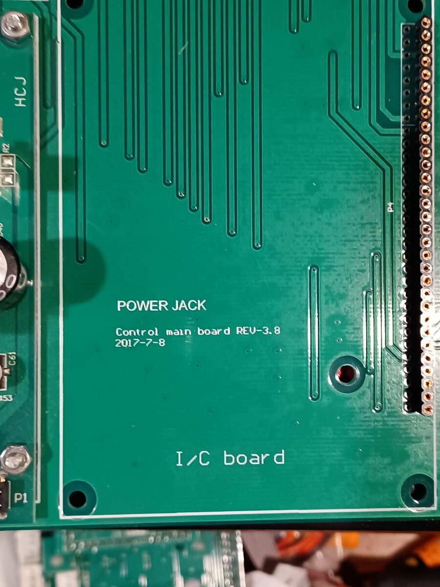
PJ Control board = 2017-7-8 Rev 3.8 (sorry I missed to add into my original post)
Can the latest control board 11.x be used to replace a Rev 3.8?
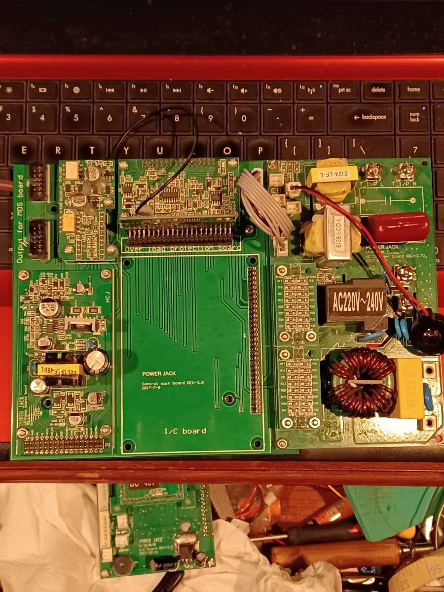
Miguel, thanks for the video. Again, I don't see how your inverter is even running with so many of the led lights off. Below are pics of the control board that was sold to me by Sean Gentry Solar as a v8 control board. Note that it says v3.8 on the board same as yours. I couldn't find anyplace on the board where it says v8. Sid, maybe you could ask Sean how to tell what version is what? There must be some significant way to tell. I have a v9 inverter but have never looked to see what it says on the control board, but it does have a v9 driver on it. (It's not available for me to check at the moment)
To the best of my (admittedly limited) knowledge, only versions 7, 8, and 9 boards have individual removable component boards (with the exception of the driver board which has been removable since wayyyy back to v2xx). My favorite older (and still working!) control board is a v3.4 and only the driver board is removable. Somewhere between 3.4 and 7 powerjack changed to the multi-board model. Version 10 was a return to a simpler single board model (still with removable driver board).
Miguel, changing from your current control board to v11 will require re-wiring of some connectors. If you are good at that sort of work, great! If not, well.... maybe it would be better to put your money into a new inverter instead. The multiple board control boards were, in my opinion, a big mistake on powerjack's fault. Overcomplicated, too many connectors, and miles of extra traces the already flaky signals had to run through. Powerjack was smart to finally go back to a simpler board design.
Best of luck whatever you decide to do.
Can anyone explain please, how to wire this combination to the transfer switch? This is a U-Power 15000w 24v PJ.
For 120/240v, do I use L1+L4 and leave N2and N3 looped as is seen in the picture? Or, do I connect N2and N3 to my
neutral bar on the transfer switch? Thank you for your help.
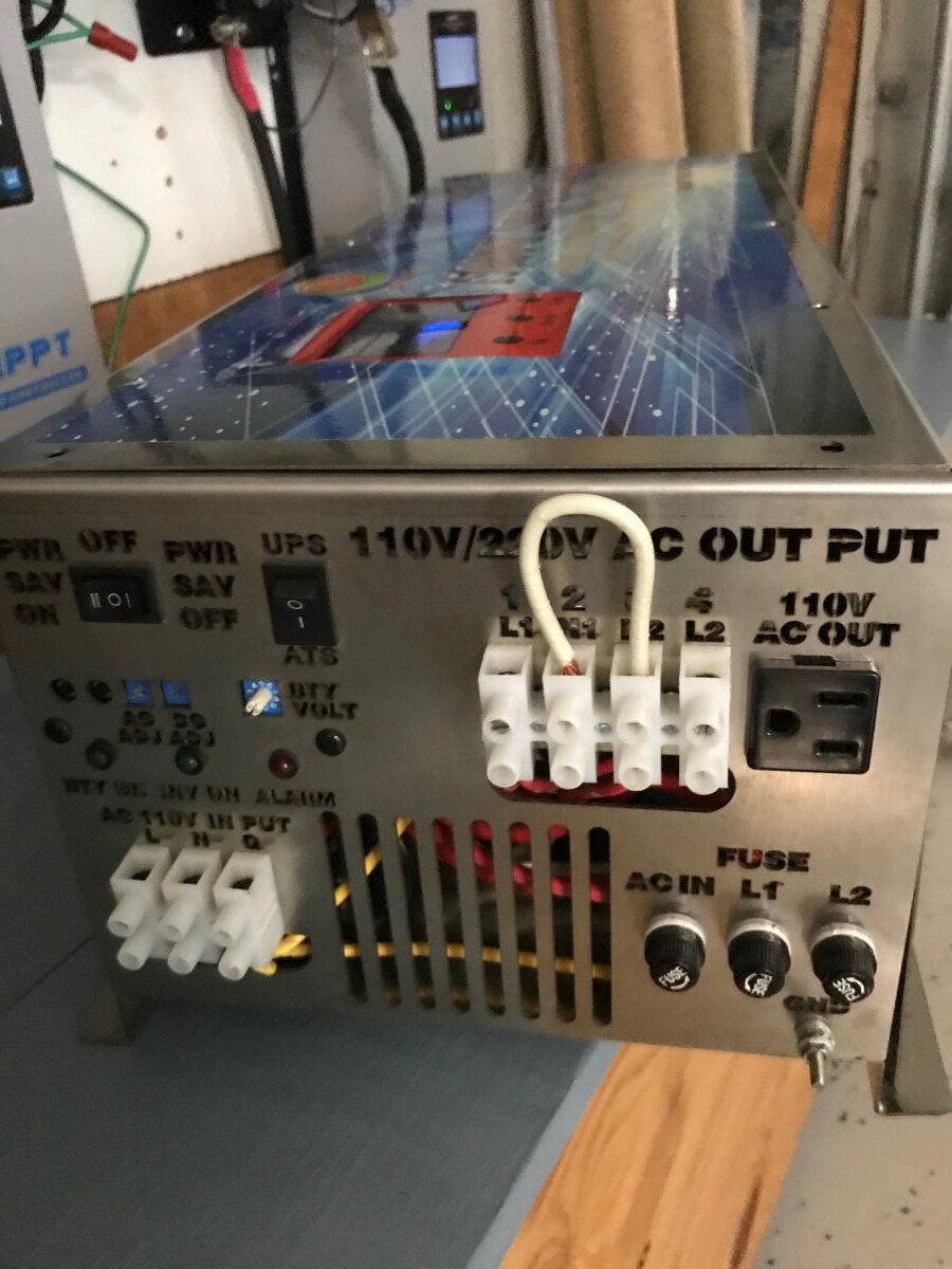
For 240v split-phase output, you would leave N1/N2 wired together as shown. And also run a wire from either N1/N2 to your Neutral bar. L1 / L2 are self-explanatory, i.e. you need L1, N, L2 to your transfer switch box.
worth noting that the numbering of the connector pins (1, 2, 3, 4) is just that: numbering the connector pins. The actual functionality is L1/N1/N2/L2.
As always, with a PJ...it's 2-3x over-rated. And U-Power 2x over-rates the PJ rating.
in other words, don't expect more than 3-4kw continuous out of this "15kw" inverter. It just isn't possible.