PLEASE NOTE: If you had an account with the previous forum, it has been ported to the new Genetry website!
You will need to reset the password to access the new forum. Click Log In → Forgot Password → enter your username or forum email address → click Email Reset Link.
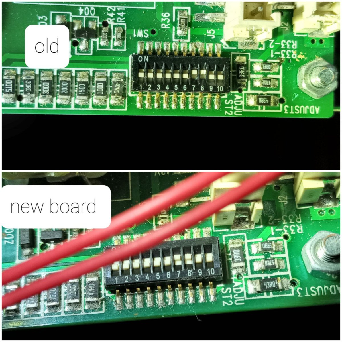
Are you sure the DIP switches that were "up" on the old board are fully "up" on the new board? They require a bit of force to fully move into the "up" position. A jeweler's screwdriver set is very handy for things like that.
I am assuming it didn't use to overload with the previous boards?
Are you sure the DIP switches that were "up" on the old board are fully "up" on the new board? They require a bit of force to fully move into the "up" position. A jeweler's screwdriver set is very handy for things like that.
That's right, with the previous boards it didn't. I understand that I put them right, just like the old board.
If it's still overloading with the DIP switches set same as the old board, then <a contenteditable="false" data-ipshover="" data-ipshover-target="/profile/1-sean-genetry-solar/?do=hovercard" data-mentionid="1" href="/profile/1-sean-genetry-solar/" rel="">@Sean Genetry Solar will have to chime in tomorrow with the official setting for the DIP switches.
If it's still overloading with the DIP switches set same as the old board, then @Sean Genetry Solar will have to chime in tomorrow with the official setting for the DIP switches.
I did, and it continues the same.
Setting copy looks good. <a contenteditable="false" data-ipshover="" data-ipshover-target="/profile/1-sean-genetry-solar/?do=hovercard" data-mentionid="1" href="/profile/1-sean-genetry-solar/" rel="">@Sean Genetry Solar will have to chime in on this. Trying to think if there's any possibility that L1 and L2 to the front panel got swapped on the control board...because the overload protection only works on one phase, not the other (go Power Jack!) However, this would only be possible if it was a 220v inverter...but the sticker on the relay says 110v. If you never got an overload error before replacing the boards, a wiring mistake could be considered.
21 minutes ago, Sid Genetry Solar said:Setting copy looks good. <a contenteditable="false" data-ipshover="" data-ipshover-target="/profile/1-sean-genetry-solar/?do=hovercard" data-mentionid="1" href="/profile/1-sean-genetry-solar/" rel="">@Sean Genetry Solar will have to chime in on this. Trying to think if there's any possibility that L1 and L2 to the front panel got swapped on the control board...because the overload protection only works on one phase, not the other (go Power Jack!) However, this would only be possible if it was a 220v inverter...but the sticker on the relay says 110v. If you never got an overload error before replacing the boards, a wiring mistake could be considered.
It could be, this inverter is not split phase, (they did not have neutral) I converted it into split phase, and the work was excellent, 120/220 was working very well. The main reason why I changed all the boards and mosfets was that I had tried to put 220v at the input of the inverter to use it as a charger but it didn't work like that, that's why it had burned out, but before that it worked perfectly even though it was that relay 110v.
9 minutes ago, Rafaelmedina23 said:It could be, this inverter is not split phase, (they did not have neutral) I converted it into split phase, and the work was excellent, 120/220 was working very well. The main reason why I changed all the boards and mosfets was that I had tried to put 220v at the input of the inverter to use it as a charger but it didn't work like that, that's why it had burned out, but before that it worked perfectly even though it was that relay 110v.
Gotta love a PJ...not refusing to pop the relay on with an invalid input voltage...!
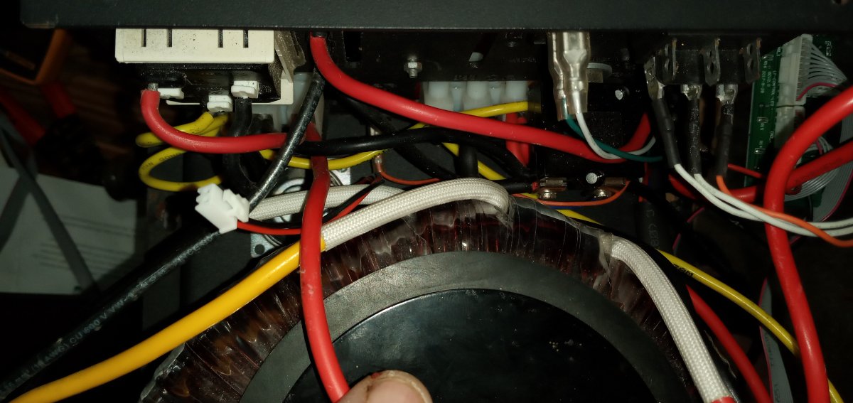
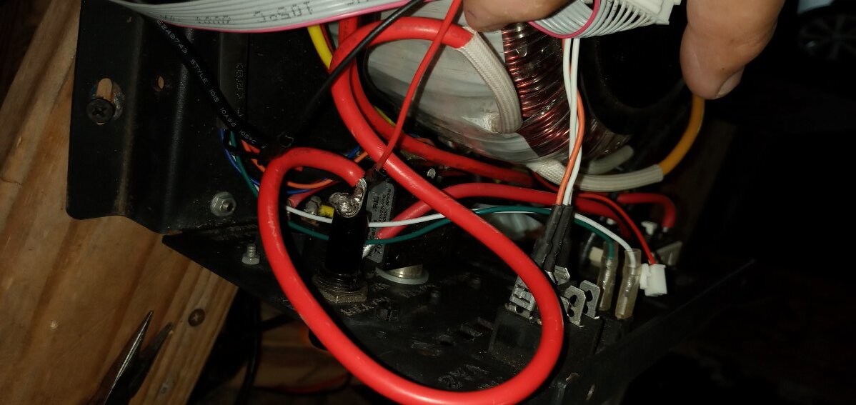
Maybe you can enlighten us on the current wiring of the transformer, which wire goes where? It sounds like the board is regulating 120vAC (i.e. L1 and Neutral go from the transformer to the control board, while L2 goes directly to the front panel, not to the board)--this being a requirement for a 120vAC charge input.
If the previous layout was running the outlet from L2 / N, while L1 / N went to the control board...then there would be no overcurrent protection on it, and you would not have encountered the overload problem.
If you changed it so the outlet is connected to the L1 output on the control board, now it will have the output current limit--which previously was only a charge current limit.
Gotta love a PJ...not refusing to pop the relay on with an invalid input voltage...!
When I did it I put all the cables in the same way, I had taken photos.
Setting copy looks good. @sean-genetry-solar will have to chime in on this. Trying to think if there's any possibility that L1 and L2 to the front panel got swapped on the control board...because the overload protection only works on one phase, not the other (go Power Jack!) However, this would only be possible if it was a 220v inverter...but the sticker on the relay says 110v. If you never got an overload error before replacing the boards, a wiring mistake could be considered.
If it were the possibility of wiring error, L2 put on L1, would this short circuit or would it go to overload?
If L2 and L1 were connected, it would short circuit/probably blow FETs. Overload only works on the L1 tap, so if the AC outlet was originally connected to the L2 circuit (the wire may have gone directly from the transformer to the AC outlet), it would not have any overload protection on it.
If L2 and L1 were connected, it would short circuit/probably blow FETs. Overload only works on the L1 tap, so if the AC outlet was originally connected to the L2 circuit (the wire may have gone directly from the transformer to the AC outlet), it would not have any overload protection on it.
That's what I mean, excuse my English, I'm from Puerto Rico, if by mistake I reversed the cables, the L1 on the L2 screw and the L2 on the L1 screw, could it go to overload?
If the outlet previously was directly connected to the transformer wire (not the control board), there would be no overload trip, so you would never have noticed it.
But if after the conversion the outlet is now connected to the mainboard, that would explain why it is now overloading, because now the CPU can see the load.
I can't clearly see the wiring in the photos, and also do not have the photos of the previous wiring; without fully understanding how it's wired, I can't provide good assistance. Just trying to figure out what changed to cause the inverter to overload now, as the DIP switches are now set (ruling that out as the cause).
25 minutes ago, Sid Genetry Solar said:If the outlet previously was directly connected to the transformer wire (not the control board), there would be no overload trip, so you would never have noticed it.
But if after the conversion the outlet is now connected to the mainboard, that would explain why it is now overloading, because now the CPU can see the load.
I can't clearly see the wiring in the photos, and also do not have the photos of the previous wiring; without fully understanding how it's wired, I can't provide good assistance. Just trying to figure out what changed to cause the inverter to overload now, as the DIP switches are now set (ruling that out as the cause).

OK, let me guess: inverter outlet was previously 120v, and you changed it to 240v?