PLEASE NOTE: If you had an account with the previous forum, it has been ported to the new Genetry website!
You will need to reset the password to access the new forum. Click Log In → Forgot Password → enter your username or forum email address → click Email Reset Link.
I bought a 12000w LF AGM, problem from day one , cannot be connected the hardwire simultaneously with the house power, tripping the grid panel breaker , with the first installed I had a push button circuit breaker on the battery but kept on blowing it I removed it then blew up all the mosfet and other parts in smoke . I now replaced all the damaged parts , with extras protection I can use the receptacle but not the hardwire if I attempt to do I will get sudden low battery warning and tripping all circuits breakers.
please any suggestions?
Thanks
<a href="/monthly_2022_12/2AEDC2D3-7B09-47CE-9107-517901328186.jpeg.a5081a0adf0d21e599e8431d83e69c4b.jpeg" class="ipsAttachLink ipsAttachLink_image" ><img data-fileid="1965" src="//forums.genetrysolar.com/applications/core/interface/js/spacer.png" data-src="/monthly_2022_12/2AEDC2D3-7B09-47CE-9107-517901328186.thumb.jpeg.eb6a74516ed6353acb1474cd29435c0b.jpeg" data-ratio="75" width="1000" class="ipsImage ipsImage_thumbnailed" alt="2AEDC2D3-7B09-47CE-9107-517901328186.jpeg">
<a href="/monthly_2022_12/3B7159B4-97F2-4EF8-A6C4-0582BE62BCC1.jpeg.4229f2337b4fc666a3deddf81a6bbb97.jpeg" class="ipsAttachLink ipsAttachLink_image" ><img data-fileid="1966" src="//forums.genetrysolar.com/applications/core/interface/js/spacer.png" data-src="/monthly_2022_12/3B7159B4-97F2-4EF8-A6C4-0582BE62BCC1.thumb.jpeg.049965d7bd5597a652e9bc1db99a7edb.jpeg" data-ratio="75" width="1000" class="ipsImage ipsImage_thumbnailed" alt="3B7159B4-97F2-4EF8-A6C4-0582BE62BCC1.jpeg">
<a href="/monthly_2022_12/27F6FD49-D665-430C-A954-7AEFBC4DA8A4.jpeg.4b728371ebecb458b84c73e17166dd83.jpeg" class="ipsAttachLink ipsAttachLink_image" ><img data-fileid="1967" src="//forums.genetrysolar.com/applications/core/interface/js/spacer.png" data-src="/monthly_2022_12/27F6FD49-D665-430C-A954-7AEFBC4DA8A4.thumb.jpeg.cc7ad39c549814320e69a3586a48dc73.jpeg" data-ratio="75" width="1000" class="ipsImage ipsImage_thumbnailed" alt="27F6FD49-D665-430C-A954-7AEFBC4DA8A4.jpeg">
<a href="/monthly_2022_12/BA3414AF-A43F-49C0-BF84-EA842BF19F3B.jpeg.4d5cce73960241d61a96987cf998cdb2.jpeg" class="ipsAttachLink ipsAttachLink_image" ><img data-fileid="1968" src="//forums.genetrysolar.com/applications/core/interface/js/spacer.png" data-src="/monthly_2022_12/BA3414AF-A43F-49C0-BF84-EA842BF19F3B.thumb.jpeg.8033361afd644cb9ae4fd80ebaca62e0.jpeg" data-ratio="133.45" width="562" class="ipsImage ipsImage_thumbnailed" alt="BA3414AF-A43F-49C0-BF84-EA842BF19F3B.jpeg">
<a href="/monthly_2022_12/0EE86634-2BCE-4A45-82E0-E46779C62C65.jpeg.57dd9c6fb969baccb010df7e1919545a.jpeg" class="ipsAttachLink ipsAttachLink_image" ><img data-fileid="1969" src="//forums.genetrysolar.com/applications/core/interface/js/spacer.png" data-src="/monthly_2022_12/0EE86634-2BCE-4A45-82E0-E46779C62C65.thumb.jpeg.7d95508f4800f3e2a2bf9db564232bb7.jpeg" data-ratio="75" width="1000" class="ipsImage ipsImage_thumbnailed" alt="0EE86634-2BCE-4A45-82E0-E46779C62C65.jpeg">
I can use the receptacle but not the hardwire if I attempt to do I will get sudden low battery warning and tripping all circuits breakers.
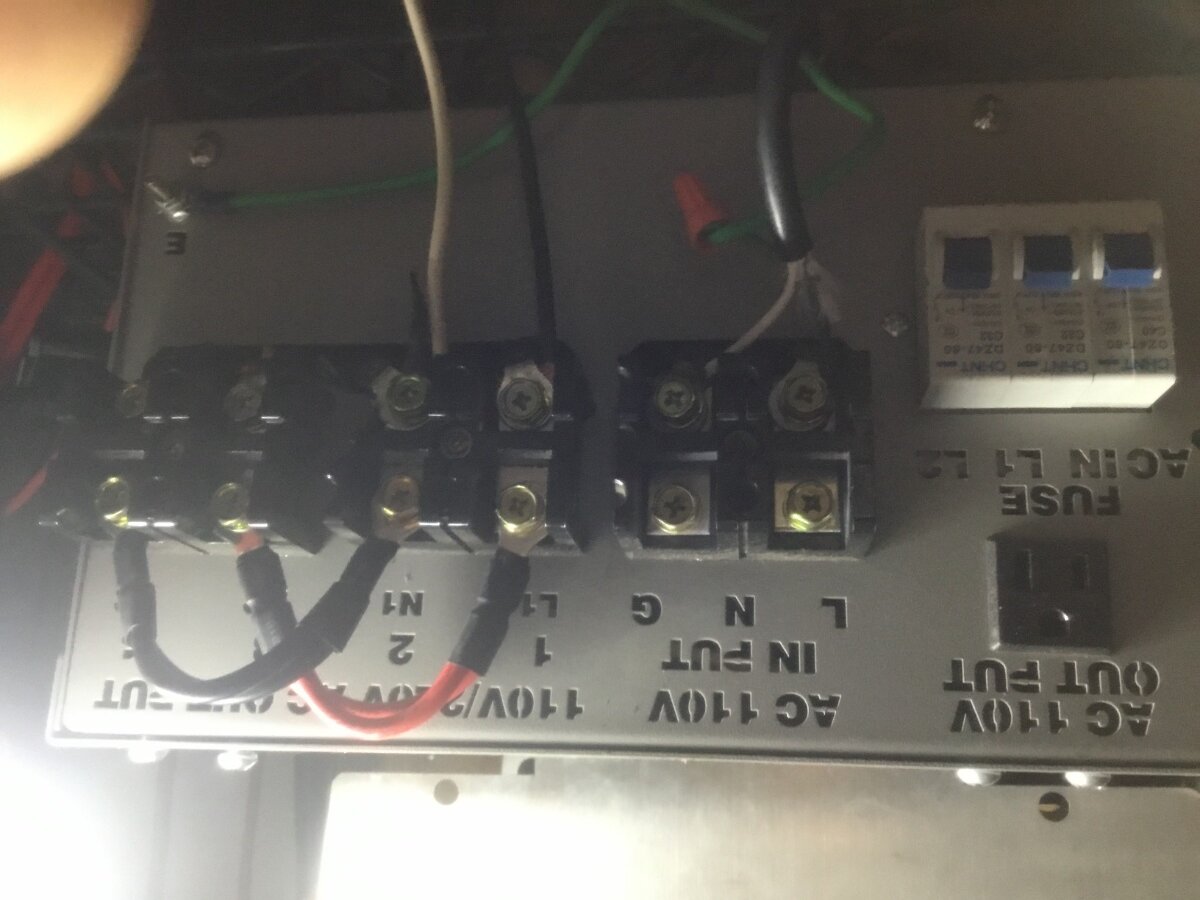
This picture is for off-grid 120vac only . This picture show the connection can not be conneted L1 N L2 to the house . Sorry but I think you MISS WIRED for the house . . SEE the ebay instruction for AMG connection .
.png.fccf6b59d8f6659965a8a53e6fe006fc.png)
cannot be connected the hardwire simultaneously with the house power,
A PJ LF inverter is not a grid-tie inverter! You WILL blow it up if you connect it to a live electrical panel.
A LF inverter must be connected to a separate breaker panel not connected to any other power source.
No. No. You missing my point. I am quite aware that unit is not a grid tied but it is a charger , ATS and UPS and it has an AC input grid connector for these options .if I use the hardwire L1 + N1 which 115v output load “ example if a fan simultaneously with AC input then AC input breaker will tripped.
Dickson , you mentioned my wiring is wrong, isn’t the hardwire block L1 + N1 = 110. L2 + N2=110 since I only have needs for 110v., as factory default double loop ….. my picture indicated L1 +N1 as per instructions.. please advise on wiring…
My 3000w is functioning on the same type of setup and options
Dickson , you mentioned my wiring is wrong, isn’t the hardwire block L1 + N1 = 110. L2 + N2=110 since I only have needs for 110v., as factory default double loop ….. my picture indicated L1 +N1 as per instructions.. please advise on wiring…
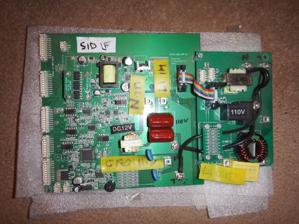
YES for 110vac at the inverter receptacle is ok and will work for 110vac appliance . Disconnect the 110vac AC input and see if it work without tripping the breaker . The factory are known for miss wired the AC charger INPUT . I know now your AMG is setup for 110vac only and the wiring is good . All my PJ inverter do not have the charger board so I cab not show how it is suppose to be wired internally . I just bought a 9kw PJ inverter and the factory miss wired the output board and I fix before pushung the start switch My 3000w is functioning on the same type of setup and options I suggest you open the 3000w and the charger board is the same as the 12000w . Check and wire both inverter the same internally . Make sure both inverter has the rev 11.3 control board .
 Dickson,
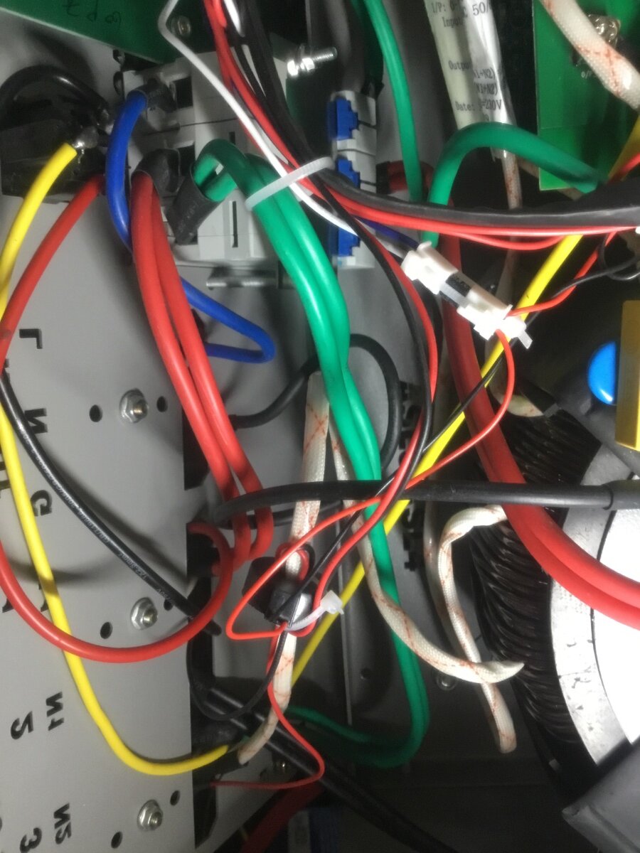
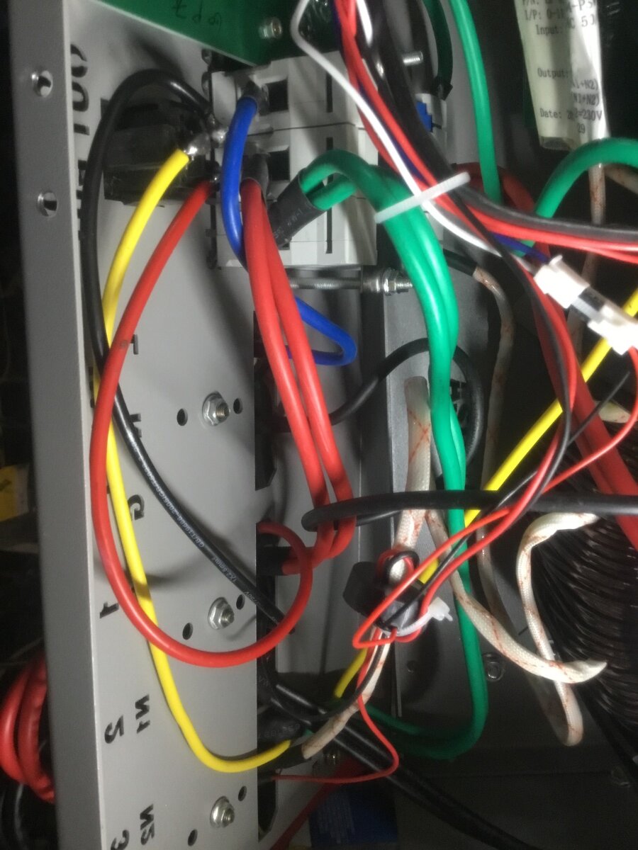
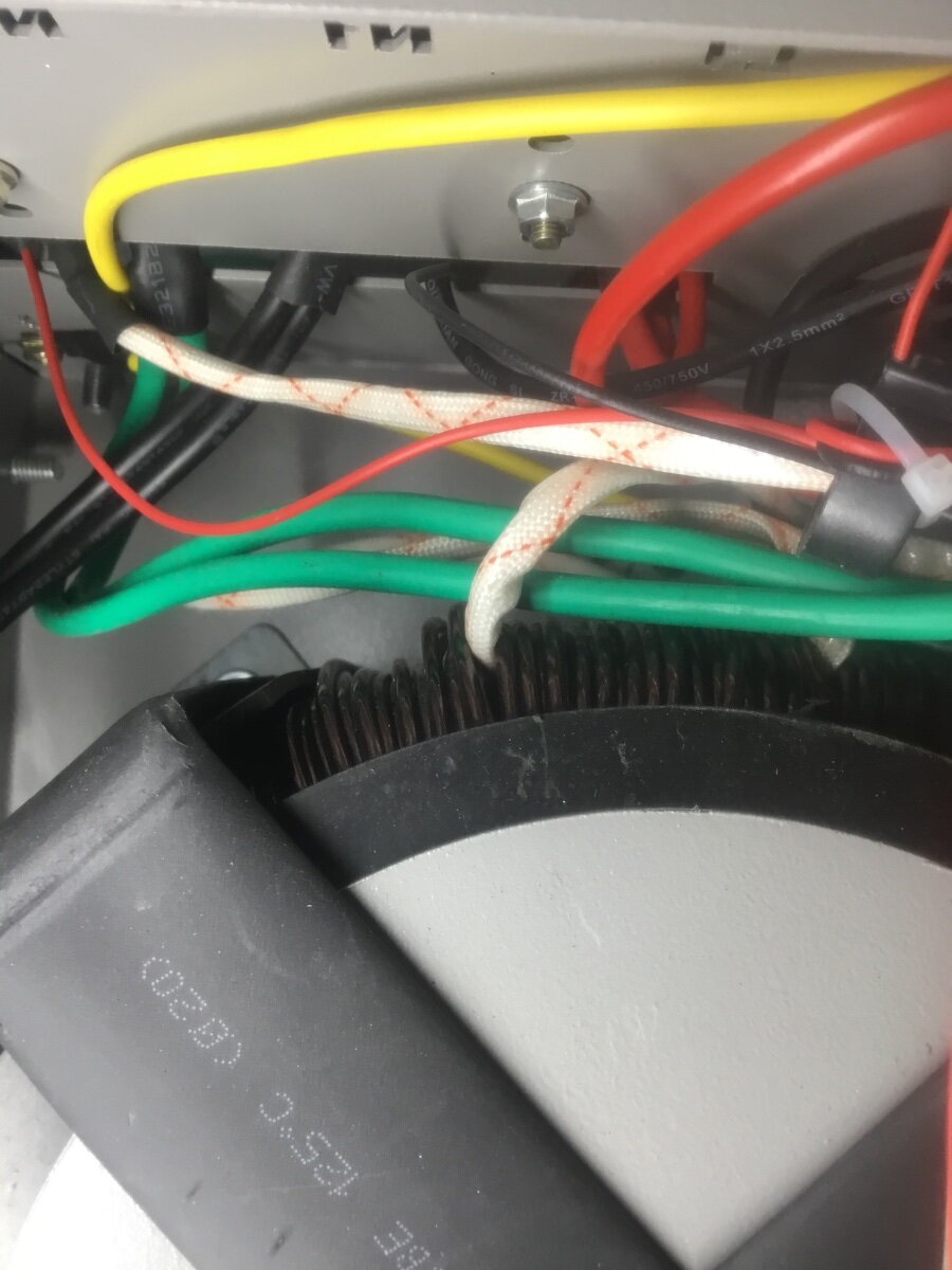
Thank you for the information I also suspected of miss wiring as well .unfortunately my other unit is a Powmr and will not help. Power jack folks are not that supportive as well I have asking for manual and wiring schematic and questioning the wiring I have not getting any response. Attached a couple pictures ( single receptacle outlet ( working fine but hardwire is the problem) ) has 3 wires B R (Y )as Ground but hardwire has an additional white with markings and with current sensor wire from the transformer although there is a same wire to breaker as well.
those folks from walnut California or China not responding from email.
Thanks again..
A possibility here (though it wouldn't explain why FETs were blowing or your battery breaker constantly tripping) could be that the AC Input wires are swapped (i.e. Neutral goes to Line, and Line goes to Neutral.)
The PJ inverter only has a single relay on the input side, supposedly disconnecting Line. Neutral is a direct pass-through.
This means that you can very easily create a dead short on the AC line across "AC Output Line" and "AC Input Neutral"--because said terminals would be directly wired together.
You can check this with a DMM set to AC volts: what voltage do you get across AC Output Neutral and AC Input Neutral. (Also check AC Output Line and AC Input Line.) Both should be ~0vAC. If you get ~120vAC, then that's likely a part of the problem. But does not quite explain the battery breaker tripping/FETs blowing (although both of those would be expected for an AC output backfeed).
If the "other inverter" you mention/show is a PowMr 3000W, then it's a completely different beast, being an HF inverter. The different set of operational rules could explain why it's seemingly working fine in a similar scenario.
with extras protection I can use the receptacle but not the hardwire if I attempt to do I will get sudden low battery warning and tripping all circuits breakers.
IT seem like you can use the 110vac receptacle without any connection to the inverter INPUT . This mean the charger board is bad or miss wired . Can you return the inverter back to the seller ? The seller and nobody from Powerjack will tell you how to repair if it is a wiring issue or if charger board is bad or control board is bad .
Sid,
Although I just purchased the unit and arrived last month from Superpower goes by many name Names on EBay ( Products description are with the same wording)I Had a couple communication with “Jelly” but suddenly went silent.I would love to return and exchange but yet to hear back Jelly after a few emails.
I did check the voltage on both block out puts as you will see
N1 + G =113 and L2 +G=113 is this normal? ( see pictures)
<a href="/monthly_2022_12/06DF5AC2-62CF-4BD5-BF9F-0CFF7FACFCEC.jpeg.be43a977960a9211e3b124f14c35f037.jpeg" class="ipsAttachLink ipsAttachLink_image" ><img data-fileid="1987" src="//forums.genetrysolar.com/applications/core/interface/js/spacer.png" data-src="/monthly_2022_12/06DF5AC2-62CF-4BD5-BF9F-0CFF7FACFCEC.thumb.jpeg.3bc06dd8e33a613905a1fba185622194.jpeg" data-ratio="133.45" width="562" class="ipsImage ipsImage_thumbnailed" alt="06DF5AC2-62CF-4BD5-BF9F-0CFF7FACFCEC.jpeg">
<a href="/monthly_2022_12/1BF31B26-C19D-40B9-B4C9-C084E65F1504.jpeg.e29b33874e8590726ddca655f5bc0918.jpeg" class="ipsAttachLink ipsAttachLink_image" ><img data-fileid="1988" src="//forums.genetrysolar.com/applications/core/interface/js/spacer.png" data-src="/monthly_2022_12/1BF31B26-C19D-40B9-B4C9-C084E65F1504.thumb.jpeg.57582ff3010d610190f08f726ee84510.jpeg" data-ratio="133.45" width="562" class="ipsImage ipsImage_thumbnailed" alt="1BF31B26-C19D-40B9-B4C9-C084E65F1504.jpeg">
I did check the voltage on both block out puts as you will see N1 + G =113 and L2 +G=113 is this normal? ( see pictures)
Well, you're measuring both ends of the black jumper wire--so of course the reading will be the same in both locations.
In short, the PJ "AMG" setup provides 2 separate 120v output taps from the transformer on these terminals. (The inverter only regulates from one of them, which is why charge is 120v input only.)
If you put the 2 output taps in series, you get 240v. And if you put them in parallel, you get 120v total output.
Technically, the chassis should be loosely floated (by 10nF decoupling caps on the output board) between Line and Neutral--so the meter should be reading ~60vAC. That it's reading 113vAC kinda indicates that the chassis is shorted to the other output line. (Check from chassis ground to the red jumper wire--betcha it'll be 0v.)
If that is the case, then if you're wiring chassis ground to breaker panel ground (which will be bonded to Neutral), you're likely deadshorting the output of the inverter due to an internal wiring issue. Which would explain all the breakers tripping & blowing the FETs when it's connected to the breaker panel.
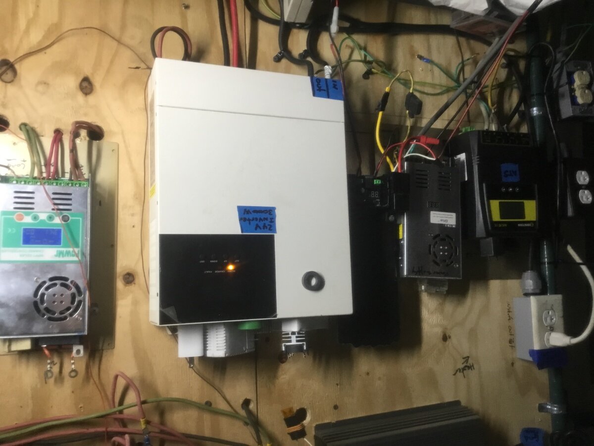
Thank you all for all these informations , as much that I would like to return this unit , the seller Superpower is not accepting return from EBay site..I am not sure how to resolve this issue . I am sure there is a wiring issue ( trying to connect power conditioner , will get ground fault error) , the picture attached is a stand-alone unit but only the batteries …
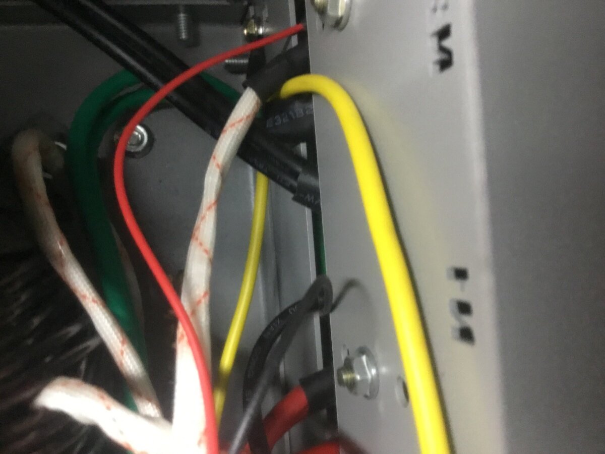
N1 and ground chassis = 114 v. , is the white wire with orange markings from the transformer should be at the blocking out L2 of course looping with N1?
N1 and ground chassis = 114 v. Miss wired at the factory . N1 to ground should 0 vac . Powerjack has floating neutral if wired correctly . I will post picture of my rev 11.1 control board tommorow . This control board is similar to to your . Superpower goes by many name Names on EBay He is David and I buy many defective parts on ebay but never leave a review .
N1 and ground chassis = 40vac when inverter is off-grid and NOT connected to house . When connected to house N1 and ground chassis = 114 v . Your inveter is usable if NOT connected to INPUT 110vac and use as off-grid 110vac only . Picture of my rev 11.1 control board with charger not connected . There is only 3 wires from the transformer input to control board and L2 go from transformer to output fuse . Ebay Picture of PJ 12000 watt connected to AC INPUT and charger . IT also has only 3 wires input from transformer . The worker has to stupid to miss wired .
.png.7c0d639fbdb70ef0c53b55f496250069.png)
//content.invisioncic.com/g308908/monthly_2022_12/B484408F-35C9-43F4-BCBD-8765D9937544.thumb.jpeg.d08ea2ba852b54328ecca3400fd164aa.jpeg
Looking at the wiring to these output blocking , I wondering if the 4th output ( white cloth red markings) wire from the transformer should be connected L2 since there is a double black coming from the AC charger board. The transformer has 4 wire out puts ( the first one to N2 and second to L2 (control board ), third to the fuse and exit as double green to N2 )) of course looking a double red wire from the charger board goes into the breaker fuse exit as a double red into L1block hardwire …. Wonder if this wiring is correct or anyone who’ has the unit .surprisingly the single receptacle wired as L1 +L2 and chassis ground working without tripping the breakers.
Thanks
Wiring to the terminal blocks would be correct if the inverter runs at no load without tripping breakers.
If you swapped transformer wires around, you likely will blow another set of FETs (by cross-wiring the transformer output taps over each other, effectively creating a dead short on the transformer output).
As it appears that the inverter runs with nothing connected to it, the issue likely has to do with the way the inverter is connected to the breaker panel and/or possible ground-neutral bonding problems.