PLEASE NOTE: If you had an account with the previous forum, it has been ported to the new Genetry website!
You will need to reset the password to access the new forum. Click Log In → Forgot Password → enter your username or forum email address → click Email Reset Link.
Ahh this is interesting. I will try this out. Cool thanks for finding that.
No luck there it doesn't acknowledge there is any data at all. I have it checking if serial is available and there is nothing, no data light either. That inverted output from the balancer just won't let it work.
if(Serial.available()){
input = "Good";
snprintf (msg1, MSG_BUFFER_SIZE, "%s", input);
u8g2.clearBuffer(); // clear the internal memory
u8g2.setFont(u8g2_font_ncenB08_tr); // choose a suitable font
u8g2.drawStr(0,10,msg1); // write something to the internal memory
u8g2.sendBuffer(); // transfer internal memory to the display
delay(1000);
}
So I've done a quick bit of bench testing with a 4-string of GS balancers.
If the ESP8266 simply doesn't have the ability exposed to handle inverted-polarity serial, you can very easily invert it yourself with a single transistor like this:
<img alt="Transistor Circuits | Electronics Club" data-ratio="75.33" style="width:300px;height:226px;margin:0px;" width="300" data-src="  " src="/applications/core/interface/js/spacer.png" />
I tested that with a CH340 TTL level->USB serial converter, and it works just fine:
<img class="ipsImage ipsImage_thumbnailed" data-fileid="2122" data-ratio="16.15" width="867" alt="image.png.f28b5c8029f5f0d0d9fd744aebf0e607.png" data-src="/monthly_2023_01/image.png.f28b5c8029f5f0d0d9fd744aebf0e607.png" src="/applications/core/interface/js/spacer.png" />
One thing I DID find? There is an error in the GS balancer datasheet: the baud rate is 4800 baud, NOT 2400 baud as listed! Mea culpa!
One thing I DID find? There is an error in the GS balancer datasheet: the baud rate is 4800 baud, NOT 2400 baud as listed! Mea culpa!
Well shoot thanks for finding that. I was using 2400 I will play with the scope a bit tonight to see if I can read it now. I ordered those RS232 boards so want to see if they work without any extra tweaking. I could make a little adapter too like you said I was thinking the same thing after sleeping on it a bit.
That did the trick for the Rigol decoder. I inverted the input and set it to 4800 and I am now reading the data. I knew it worked, but one of those things that I like to see it myself.
I am trying to decide how to use the balancer status and voltage string. I think I get it your doing a 7bit for the letter status and 9bit for the number for the voltage. Just the system is grouping them into two 8bit segments I am thinking I need to convert them to binary combine the two segments into one binary string and then substring them so I have the 7bit and 9 bit binary strings then convert them.
I completely understand I may be completely overthinking this, so thought it was best to type this out and see if there is an easier way to accomplish this. I might be missing something very obvious so don't shoot me man.
24 minutes ago, AquaticsLive said:I might be missing something very obvious so don't shoot me man.
Haha, hehe ;-).
Most user-friendly way I know of would be to use a named bitstring type, like this:
typedef union {
    struct {
        unsigned int Voltage       	:9; // bits 0-8: battery voltage

        unsigned int Unused        	:3; // bits 9-11: unused
        unsigned int Balancing     	:1; // bit 12: "Balance Active"
        unsigned int Tripped		:1; // bit 13: Tripped
        unsigned int Cooldown		:1; // bit 14: self cooldown active
        unsigned int Failed			:1; // bit 15: Failed

    };
    struct {
        unsigned int LowByte        :8;
        unsigned int HighByte 		:8;
    };
    struct {
        unsigned int All;
    };
} BAL_Flags_t;
extern volatile BAL_Flags_t BAL_Flags;
to use, put the 2 bytes in BAL_Flags.LowByte and BAL_Flags.HighByte -> read the voltage out with BAL_Flags.Voltage, etc., etc.
You can also manually "stack" the bytes in an unsigned int and then bitmask to get the specific bits/bit regions. Which is all the above is literally doing, just in a more concise way.
16 hours ago, Sid Genetry Solar said:You can also manually "stack" the bytes in an unsigned int and then bitmask to get the specific bits/bit regions. Which is all the above is literally doing, just in a more concise way.
Thanks for explaining, also made the manual binary info make more sense too. I get it now and I have a plan on how to map out the fields in my project. This is something I can only spend a a little bit of time per day on so works out good, I can hit a stopping point and ask questions. I was staring at the sheet last night trying to decide on what to do.
1 hour ago, AquaticsLive said:Thanks for explaining, also made the manual binary info make more sense too. I get it now and I have a plan on how to map out the fields in my project. This is something I can only spend a a little bit of time per day on so works out good, I can hit a stopping point and ask questions. I was staring at the sheet last night trying to decide on what to do.
So you could iterate down through the array like so (in pseudocode):
idx = 0;
if (array[idx++] == 0xA7) {		// post-increment moving from "transmission start" to "field start" byte
  	while (array[idx] == 0xFF) {
      // [idx + 1] = balancer version
      // [idx + 2] = highbyte, data
      // [idx + 3] = lowbyte, data
      // [idx + 4-6] = reserved
      unsigned int Vals = (array[idx + 2] << 8) | array[idx + 3]);		// manually stack the bytes
      Volts = Vals & 0x1FF;		// binary mask for just the lower 9 bits
      Fail = Vals & 0x8000;		// bit 15.  (Assign to bool variables.)
      Cooldown = Vals & 0x4000;	// bit 14
      // etc.

      idx += 7;					// skip to the next set of bytes
    }	// will loop until a 0xFE "checksum byte" is found.
} // if array doesn't start with 0xA7, it's an invalid string.
FYI the above code is not tested...at your own risk 😉.
Basically, it iterates through a received array until a non-0xFF byte is found (indicating end of string).
Each iteration should be another cell's values; you could store these in an array of values.
FYI the above code is not tested...at your own risk 😉.
Thank you no worries, this is all in the fun part. You rock you got me past parts that I was having trouble with and I know your super busy.
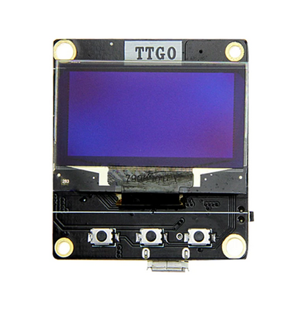
Got that little RS232 board today so now on 3D drawings to make a little case. This is the ESP8266 I am using handy little guy with the display. I have a few of them now for little wifi projects.
Update on the project I have it decoded to serial data, have been busy so hasn't been a lot of time to work on this. My code is a mess right now so will be working on splitting up the process into separate methods. Essentially the process reads the data it comes in as decimal and string data for the ones but split up in HEX bytes so I convert it HEX and then take the HEX and convert it to binary then take that full output string and read the values. The double conversion process wasn't my plan, but found that it gave me the most reliable results because of the way the serial read on this ESP board splits up the data. Anyhow here is a sample from my serial monitor. I am working on MQTT next after cleaning my code and adding notes.
Its built to allow for any number of cells, I have tested with 4S and 8S just to make sure it works dynamically.
18:27:17.700 -> XXXXXXXXXXXXXXXXXXX Packet Start XXXXXXXXXXXXXXXXXXXXX
18:27:17.854 -> Total Cells: 4
18:27:17.854 -> Cell #1
18:27:17.901 -> Balancer Ver: 1
18:27:17.954 -> Balancer Status: Normal
18:27:18.001 -> Cell Voltage Reading: 3.41
18:27:18.054 -> Cell #2
18:27:18.054 -> Balancer Ver: 1
18:27:18.101 -> Balancer Status: Normal
18:27:18.155 -> Cell Voltage Reading: 3.41
18:27:18.202 -> Cell #3
18:27:18.202 -> Balancer Ver: 1
18:27:18.255 -> Balancer Status: Normal
18:27:18.302 -> Cell Voltage Reading: 3.43
18:27:18.356 -> Cell #4
18:27:18.402 -> Balancer Ver: 1
18:27:18.402 -> Balancer Status: Normal
18:27:18.450 -> Cell Voltage Reading: 3.41
18:27:18.555 -> Full Voltage Reading: 13.66
MQTT added to the project. I will be tinkering around with a web configuration for it next so the settings aren't hard coded.
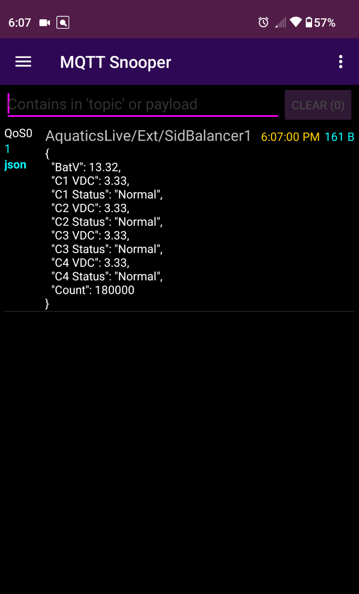
Curious what the "Count" is?
Curious what the "Count" is?
I am using that is the heartbeat so tell me if the message is new. Just sending millis so not very useful, but gives me an easy way to just look and see if something locked up.
So final plan for this project is to send messages to my charger and adjust the amperage via a digital pot to allow the battery to balance without overheating the balancer.
Fun project for sure, good for winter time.
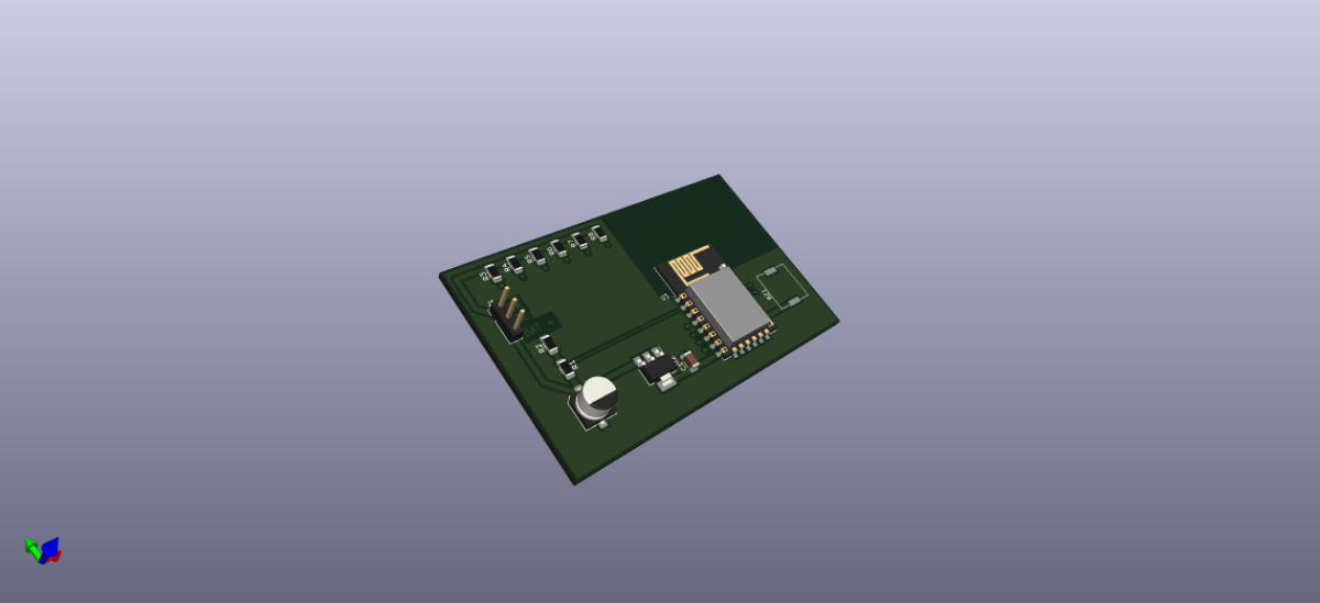
Quick update on this I made PowerMax ESP Charger board that interfaces with the balancers over MQTT. Working on a new balancer interface board too, but so far it has been working really good for the last two months Really nice to have a charger to can adjust based on the cell balancing that is high amperage the PowerMax is 100 Amps. Here is a picture on the charger board. Its way bigger than is needs to be, but did that on purpose to make it easier if someone wants to hand solder it and the price is the same. The 3d viewer has one unpopulated spot it is a buzzer and you don't really need it but it does give you audio the SMD Piezoelectric I am using isn't very loud just there to give me information of what if going on without having to look at a screen at night if I am running the generator.