PLEASE NOTE: If you had an account with the previous forum, it has been ported to the new Genetry website!
You will need to reset the password to access the new forum. Click Log In → Forgot Password → enter your username or forum email address → click Email Reset Link.
I too really admire Poida (Peter Burtles) from The Back Shed forum.
We are both in Melbourne but have never met.
i did truly think Sid was poida for a very long time
If any one likes the charge controllers they use i and others would like to hear about it
There is not any "cheap" mppt charge controllers besides msb that i have seen
I guess even some of the ones that cost the most can be even cheaper than msb
That is if they are built to last and have great customer service for parts or repair incase you have problems
I have read horror stories about the best name brand products nowadays
I dont like to gamble if some thing cost more than around 100 bucks but to be fair what can 100 bucks by now days?
I guess 5 or 600 bucks for a charge controller is still kind of cheap if it lasts 10 or more years?
There is people with way more wisdom on this subject than me that could school us all and maybe already been trying lol
There is not any "cheap" mppt charge controllers besides msb that i have seen
YES I only connect 2 solar panels per MSB and no problem for 3 years . Aliexpress sell MSB now .
If any one likes the charge controllers they use i and others would like to hear about it
The MPPTs I'm currently recommending--with some caveats--are the Epever Tracer xxxx-AN series.
The pluses:
- Fanless design.
- Nicely designed, with comm interface support built right in.
- true MPPT tracking
The only minus:
- very slow regulation: you'll need to set the "high voltage cutoff" to prevent it from overvoltaging the batteries.
- requires the MT-50 meter (or computer connection) to set it up. This is not unusual.
Just to kick start this thread back into life..........
The perturb and observe MPPT algorithm is generally accepted as the best approach to tracking solar panel loading over the full operating envelope of our solar panels.
It is not without its problems, such as locking onto false peaks caused by partial shading, and slow response to massive changes produced by passing fluffy white clouds in an otherwise clear blue sky. It does have the advantage of being reasonably idiot proof, as the MPPT software will try to find a peak with unknown or miss matched panels.
I was intrigued by all this, and a few years back decided to try a method of power tracking that was totally different and a lot simpler. To cut a long story short, what I did was build a simple buck converter that I could control the duty cycle manually, with a potentiometer from 0% to 100% duty cycle. This was hooked up to one 30v panel and a 12v car battery, all monitored by a Turnigy power meter. The power meter was on the solar side of the buck converter and displayed volts, amps and watts.
The original aim was to test and compare various panels I had here at the time.
I was rather surprised to find that I could adjust the solar panel voltage over a much wider range than I had expected, and the measured power remained much more constant than I had expected. Sure, there was a definite point of maximum power, but it was not the peak I was expecting, but a very broad almost flat hump, and the power maximum hardly changed over a very wide operating voltage range. The power maximum was always pretty close to the max power voltage printed on the rating plate of the panel, over pretty much everything from twilight to mid day full sun.
Power varied hugely over a full day, but the trick is to optimally load the solar panels just enough to hold the solar panel voltage constant.
If the sun gets blocked by a cloud, reduce panel loading, in full sun increase panel loading, its as simple as that.
So what I did was build a buck converter with feedback that adjusted the duty cycle to hold the solar voltage constant. In effect a simple straightforward PWM shunt voltage regulator. The same regulator had a second control loop that regulated the battery voltage to a maximum charging voltage.
In effect, it would bulk charge up to the set battery voltage holding the solar voltage constant. It would then taper the charging current down to zero in the usual way, allowing the solar voltage to rise as the duty cycle throttled back to zero.
This worked so very well, I decided do some back to back testing with an MSB solar controller, using two Turnigy power meters, two identical halves of my main solar array feeding into the same battery. To my utter amazement there was no measurable difference in performance during bulk charging under everything from full sun in a clear sky to total evil grey cloud cover. I did swap solar panels and power meters around, but the results were always within a very few percent of each other. Maybe two or three percent.
My biggest problem was that it was impossible to set both controllers to identical output voltages. Even just a few millivolts difference would cause one controller to stop charging while the other continued to trickle charge at very low current for several hours, which skewed the total amp hour readings. Its only a fair test when bulk charging.
Anyhow, my conclusions were that the biggest difference in efficiency was more due to to the power components than the charging algorithm. I could make my buck converter either more or less efficient than the MSB controller by changing mosfets and choke, and that was reflected by heating of the controllers.
The MSB perturb and observe was definitely superior in extremely poor solar conditions. The difference was something like 15 watts from the MSB controller and 10 watts from my controller from 1Kw worth of panels in twilight conditions. I don't think that really matters in the great scheme of things.
On the other hand, in rapidly changing solar conditions, such as passing clouds, my controller was much faster. Milliseconds versus several seconds to adjust.
It might be argued that a proper perturb and observe software algorithm with a two dollar microcontroller is still better and costs no more.
My circuit has the advantage of extreme simplicity, its easy to home build, easy to understand, and easy to diagnose and repair. Its just a standard analog PWM control chip and a few resistors and capacitors. The power components would be the same in either case.
If you need a 100 amp controller, its just as easy to build ten 10 amp controllers and run one per series string of panels. Also, you can build it with 600 volt (or higher) voltage mosfets if you want, plenty of choices on how to build something like this.
This may be of interest to some of you here, but my experience on the Forums is that the majority would rather just buy cheap Chinese and grumble about all the problems and disadvantages.
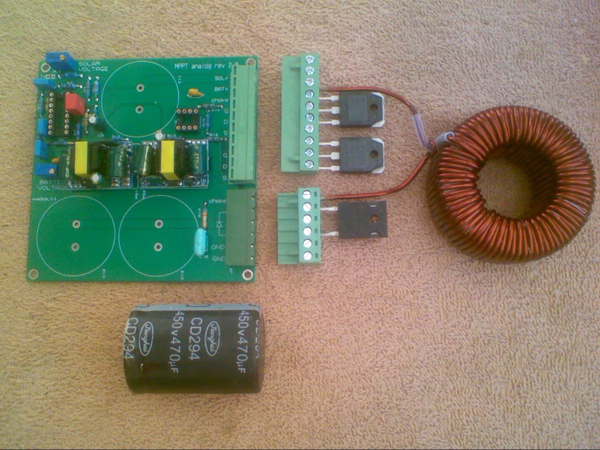
Below is a picture of the very first prototype board during construction. It was built to be very easy to fix if it blows up. Mosfets can be changed with a screwdriver, and the whole control board just plugs into the main wiring and power components.
I am still running my MSB controllers right now because they are still working. If they die or blow up, they will definitely be replaced by my own constant voltage controller.
Too many other projects on the go here right now, this is now on the back burner, but I will definitely come back to this.
The MSB
Look like an easy way to connect mosfets without soldering the mosfets .
I was rather surprised to find that I could adjust the solar panel voltage over a much wider range than I had expected, and the measured power remained much more constant than I had expected. Sure, there was a definite point of maximum power, but it was not the peak I was expecting, but a very broad almost flat hump, and the power maximum hardly changed over a very wide operating voltage range. The power maximum was always pretty close to the max power voltage printed on the rating plate of the panel, over pretty much everything from twilight to mid day full sun.
I had actually noticed exactly the same thing...not from real life, but from reading solar panel datasheets. I noticed that the maximum power point voltage was pretty much the same across the entire light range.
This gave me a naughty idea: if the user could enter the solar panel's datasheet max-power-point voltage (and temperature coefficient) into the settings of a GS MPPT, some software trickery could be used to not only handle very quick regulation via CV (constant-voltage) methodology, there was another wrinkle that could be thrown in. If the code could reasonably tightly pin down the actual max power point of the panels, we could utilize the panels' temperature coefficient to literally determine the panels' surface temperature! Once the temperature is known, we could use other coefficients to determine how close to max generation power the panels actually are (i.e. calculate solar irradience)....on and on it goes.
Just for clarity in how much I can string math together to generate useless stats, there's a "Transformer Efficiency" stat on GS inverters--the inverter calculates the losses in the transformer based on the measured (and calculated) voltages. Curious...yes. Useful...not so much 😉.
If you need a 100 amp controller, its just as easy to build ten 10 amp controllers and run one per series string of panels.
To some extent...though from a manufacturing perspective, ten 10A separate controllers would have a LOT of redundant parts and significantly higher total.
Also, you can build it with 600 volt (or higher) voltage mosfets if you want, plenty of choices on how to build something like this.
Just my personal 2 cents...when dealing with high voltages like that, IGBTs often present a much lower total loss. MOSFETs are good for lower voltages (<150v or so), whereas IGBTs often have lower losses when dealing with higher voltages (>200v or so).
It's funny how that works...I've been asked several times "why don't you just use one of those 600A IGBT blocks for a 12v inverter?" Losses are literally unfathomable when compared to 40v MOSFETs! Yes, they're used in electric cars to switch insane amounts of power--but they're also liquid-cooled for a reason! Their series losses are the same if you're switching 12v @ 600A as if you're trying to switch 800v @ 600A. One of those two is significantly more power--but the DC loss will be the same! (Switching losses obviously will be significantly higher at the 800v mark, but that's besides the point at hand.)
This may be of interest to some of you here, but my experience on the Forums is that the majority would rather just buy cheap Chinese and grumble about all the problems and disadvantages.
Hear 'ya there 😉. I've started on theory for a GS MPPT--but due to everything else significantly more important, that's way down on the project priority list at the current time.
It'd be a 100A size--and the challenge of course is how to do that without generating a heap of heat. And being unique enough to stand out in a market saturated with Chinese products.
Milliseconds versus several seconds to adjust.
I have a feeling that the reason a lot of the cheap Chinese controllers are SO SLOW is because they're using long-term averages as a Band-Aid over sloppy regulation code, to avoid regulation oscillations.
Anyhow, my conclusions were that the biggest difference in efficiency was more due to to the power components than the charging algorithm. I could make my buck converter either more or less efficient than the MSB controller by changing mosfets and choke, and that was reflected by heating of the controllers.
I would think that a synchronous buck converter--though much easier to blow out--would be far more efficient at higher currents. At lower currents (i.e. 10A), a diode does function pretty well (though dissipating an easy ~10W of heat alone)...but at higher currents, you kinda HAVE to go synchronous just to keep the losses down!
Playin' with the choke...that's a "no experience" area for me, though it literally is the heart of the MPPT! Weird stuff like switching frequencies, skin effect, ferrite composition....
Agree with everything you say Sid !
This constant solar voltage idea has bugged me for years, so I just had to try it. My situation is different to most, I am running a 96 volt system, so currents are much lower for me. The fact I design and build all my own equipment, its no more difficult to do it for 96v as for any other voltage.
If combined max power on the rating plates work out to say 130 volts for example, and you swing the solar voltage regulating adjusting potentiometer between 110v and 150 volts, the power might fall off only by about five percent below the peak at 130 volts. Correcting that 130 volts for temperature would certainly be possible, but hardly worth the trouble. The non criticality of the actual regulated solar voltage is absolutely astounding.
What DOES matter is loading the panels correctly. Even a small change in insolation has a very large effect on panel voltage at a given duty cycle. That is the change that must be tracked.
Setting the regulator voltage to 120v, 130v, or 140v makes no real difference. What matters is keeping the voltage within that range as the power potential of the panel goes from zero just before sunrise, to peak power at solar noon, and back to zero just after sunset.
I run IGBTs in my Warpverter, and at low power, typically a few hundred watts, the voltage drop across my 200 amp rated IGBTs is quite low. Only at the multi kilowatt output level do IGBT conduction losses start to become even noticiable. For a typical domestic inverter, the average power will be quite low compared to the peaks throughout the day, which are never very long lasting.
IGBTs have come a very long way in recent years, and would be well worth considering for a higher voltage solar controller. After all, IGBTs are now petty universal in higher voltage commercial grid tie inverters.
Synchronous buck converters are definitely the way to go for lower voltages and higher current, but caution is required because a synchronous buck converter is bi directional for power flow when charging a battery. Current can flow backwards through the choke and the "synchronous" diode, turning a buck converter into a boost converter in the reverse direction. That particular problem is not widely known or discussed in the literature. There are ways around that of course, but if writing software, the duty cycle must never become so short that current can reverse through the choke. The very high voltages created on the solar side can be particularly destructive of mosfets and electrolytics.
Magnetics design has been a particularly interesting area for me, and also pretty important in a buck converter. Its pretty difficult to make something that is small really efficient. Big may not be beautiful, or cheap, or easy to house, but something that runs cool needs to be larger than what is usually found in most Chinese designs.
Its possible to home build something that works much better, but the cost of the parts can easily exceed the cost of buying a ready made cheap Chinese product.
That is particularly true of Lithium cell balancing circuits. The manufacturers all seem to be striving to undercut each other in cost, rather than trying to sell something that is genuinely superior in performance. Unfortunately to make something decent would never sell, everyone is looking for a bargain.
Fastest way to go bankrupt in this industry is to make a solid reliable well performing product that nobody is prepared to pay for. Everyone just wants cheap.
Even giving full technical details of how to build your own SIMPLE and efficient solar electronics, its all just too much trouble, nobody is interested.
Correcting that 130 volts for temperature would certainly be possible, but hardly worth the trouble. The non criticality of the actual regulated solar voltage is absolutely astounding.
I wasn't saying that I'd "correct for temperature", as much as a very, very slight "perturb and observe" from the "base MPP voltage" to try to find the actual peak power point--and then when comparing the actual to the room temperature nominal, we could use the temperature coefficient to calculate the actual solar panel temperature. A geeky stat to display, with absolutely no usable value 😉.
hardware
Current can flow backwards through the choke and the "synchronous" diode, turning a buck converter into a boost converter in the reverse direction. That particular problem is not widely known or discussed in the literature.
I actually came across an application note that utilized this exact methodology for a battery system. I wouldn't be surprised if it's what Tesla uses in their Powerwalls--as to my knowledge, though the output voltage is in the 300-400v range, the internal cell voltage is all of 48v.
There are ways around that of course, but if writing software, the duty cycle must never become so short that current can reverse through the choke.
An alternate option is to use a powerful enough PWM module that a fixed "high side FET" pulse width can be used--then it doesn't matter what the PWM duty cycle is.
Or hardware synchronous rectification...completely alleviating the MCU requirements!
I run IGBTs in my Warpverter, and at low power, typically a few hundred watts, the voltage drop across my 200 amp rated IGBTs is quite low. Only at the multi kilowatt output level do IGBT conduction losses start to become even noticiable. For a typical domestic inverter, the average power will be quite low compared to the peaks throughout the day, which are never very long lasting.
Well, anything at no load shouldn't generate much heat 😉. But the number of GS customers who run their 6kw inverters at long-term redline might surprise you. Me personally, I've designed things to be hyper efficient--so my house inverter rarely runs past 3kw continuous anyhow. But for everyone else...
My reference to IGBT/FET losses is always based on "max rated load", and calculating losses. For a "12v" example:
- a set of 12v FETs at 1.4mOhm each / 6 per block = DC resistance of 0.233mOhm total @ 600A = 83.88W. So across a full H-bridge, we'd have 167W of heat. Not horrendous.
- pick a 600A IGBT module out of the clear blue sky: CM600HU-12F. The vCEsat (collector-emitter saturation voltage at full on) is 1.6 to 2.2v. So 1.6v @ 600A = 960W of heat (2.6mOhm equivalent)--oh, and there's a second one in the an H-bridge power path, so 1,920W of heat in the IGBT modules alone! On the bright side, this is a 100% efficient space heater that generates a tiny bit of AC output power on the side as a bonus 😉.
- obviously, losing 3.2v out of 12v is practically devastating for headroom!
If I should flip the math to 400vDC, the IGBT module would be the clear winner over a MOSFET of the same voltage rating.
That is particularly true of Lithium cell balancing circuits. The manufacturers all seem to be striving to undercut each other in cost, rather than trying to sell something that is genuinely superior in performance.
Daly BMS and other units that provide a pitifully useless 0.03A balance current--and who ever thought that using 22AWG wires to "steer" huge off-grid battery banks would work?? That's like using a spiderweb to rein a horse.
But oh boy do those toys sell like hotcakes.
more later 😉
Fastest way to go bankrupt in this industry is to make a solid reliable well performing product that nobody is prepared to pay for. Everyone just wants cheap. ......... Ebay sell 96v inverter of 6000w . Your 96v Warpverter can not sell for a lower price even if the parts come from China .
Even giving full technical details of how to build your own SIMPLE and efficient solar electronics, its all just too much trouble, nobody is interested. ......... I would be interested if your Warpverter is 96v to 120v . The only 96v inverter I know come from China . I have a battery system of 120vDC that can use a 96v inverter . Thank you .
With respect to limiting duty cycle with a synchronous buck converter.
With a buck converter that has a conventional diode, you can reduce the duty cycle right down to zero easily enough when the battery is at the fully charged maximum voltage. That is quite simple to understand, and never a problem.
With a synchronous buck regulator, reducing the duty cycle to 0%, the upper pass mosfet will then be permanently off. The lower freewheel mosfet will be actively switched on for 100% of the time. Its definitely going to go bang if you do that.
If the duty cycle is say 10%, the lower mosfet will be on for 90% of the time. During that 90% reverse current in the choke will ramp up. When the lower mosfet finally turns off, and the upper mosfet turns back on, the energy stored in the choke will be released. That energy will raise the solar voltage to 90/10 or nine times the battery voltage. That is 432 volts for a 48v battery.
With 5% duty cycle it will be 95/5 or nineteen times the battery voltage, maybe 912 volts. Small duty cycles can be very destructive, so beware of this problem when writing software to drive a synchronous buck regulator.
Synchronous buck regulators are used all the time for generating low dc voltages at very high current without any problems at all, PROVIDED the dc load is passive (resistive). Things can change rather dramatically when charging a battery, or even with a very large output capacitance that can force significant current backwards through the choke and lower mosfet.
IGBTs have several advantages, in spite of the high published voltage drop at full rated current. Assuming a 2v drop, a 48v volt inverter might lose 4% for one IGBT and 8% for two in series which is highly significant. At 96v though, its only half that, and quite practical even at higher power. That voltage drop is at full ratings, but if you use a much higher rated IGBT than really necessary, the voltage drop will be much lower in practice.
The biggest advantage comes from surge power capability. Mosfets when turned on behave like resistors. Power dissipation (heating) rises proportional to the square of the current. A 300% momentary inverter overload, generates nine times the explosive heat release in a mosfet, and that can easily be fatal.
An IGBT has a reasonably constant voltage drop at very high current, rather like a diode. If there is a 300% surge load, the current certainly goes up by that amount, but the voltage across the IGBT does not, and the explosive heat release might not be much more than three times, not nine times as with a mosfet. So IGBTs are massively more robust for the kinds of inverter surge loads we often see when starting motors for example. IGBTs can often be protected by fuses or a circuit breakers, mosfets blow up far too quickly for that !
Mosfets are still much better at 48v and probably always will be. At 96v and above IGBTs can really shine.
Fastest way to go bankrupt in this industry is to make a solid reliable well performing product that nobody is prepared to pay for. Everyone just wants cheap. ......... Ebay sell 96v inverter of 6000w . Your 96v Warpverter can not sell for a lower price even if the parts come from China .
Warpverter can be built for any input or output voltage, because the transformers need to be custom wound anyway. Nominal input voltage covers a 2:1 range. My own inverter operates from 90v to 180v dc input. Unfortunately the cost of winding transformers commercially prices the whole exercise beyond anything that can succeed in the marketplace. But for a DIY home project it offers a very interesting alternative, especially at higher power levels.
Secondhand large toroidal transformers can often be sourced cheaply for scrap prices or even free from dumpsters or salvaged from blown up grid tie inverters. It a huge amount of work stripping and rewinding these, real character building stuff !! but it need not be expensive. I suppose it depends on how you value your time. Many of us are retired and have more available time than money....
Warpverters are very easy to get working because all the high power switching is done at a very low frequency, so layout and wiring is very non critical. Big slow IGBT power blocks with ratings of hundreds of amps work wonderfully well and are pretty indestructible and available either new or secondhand.
Pure sine wave high frequency PWM inverters that switch at a frequency around 400 times higher, and require multiple parallel connected mosfets become very critical in layout, and can be much more prone to blowing up, and it becomes increasingly more difficult to do it all at higher power levels. High frequency PWM requires fewer parts though, and for lower power, up to say 4Kw or 5Kw probably a better choice, and definitely cheaper to build.
At higher power levels the Warpverter scales up much more easily, and there is really no upper practical power limit. Also building a Warpverter for the the split phase 110/220v US power system would be no problem, although its not yet been done as far as I know. The rest of the world mostly uses the three phase system, usually 230v.
There is a lot more information about Warpverters on The Back Shed Forum if the whole concept is of any interest. All the information to build one is free and open source, and readily available. I am not trying to sell anyone anything. There are now about twenty successfully built and running around the world that I know of, all are in the 5Kw to 8Kw class. A worthwhile home project to consider, but commercially the transformers are just too expensive to wind using all new materials.
1 hour ago, Warpspeed said:An IGBT has a reasonably constant voltage drop at very high current, rather like a diode. If there is a 300% surge load, the current certainly goes up by that amount, but the voltage across the IGBT does not, and the explosive heat release might not be much more than three times, not nine times as with a mosfet. So IGBTs are massively more robust for the kinds of inverter surge loads we often see when starting motors for example. IGBTs can often be protected by fuses or a circuit breakers, mosfets blow up far too quickly for that !
Not quite so fast. Here from the CM600 IGBT module datasheet:
<fileStore.core_Attachment>/monthly_2023_05/image.png.4c9f0e7f886d348a895859f0070376ea.png
It's rated 1.6v @ 600A. Notice at 1200A it's past 2v. If you take it to a 3x surge, the saturation voltage will be still higher.
Other notes:
- "explosive heat release" is most often a problem internal to the chips, i.e. the internal structure of the IGBT/FET does not have the ability to dissipate the heat fast enough--resulting in chip failure. (In the CM600, this spec is Rth(j-c), the thermal resistance between the switching junction and the heatsink tab of the module.)
- IGBTs are not "indestructible"--as a matter of fact, most "serious" IGBT drivers have "desaturation detection", which literally measures the collector-emitter voltage across the IGBT when in "on" state. If it exceeds reasonable "saturation voltage" (i.e. the current going through it has far exceeded the maximum, and the IGBT has "lost" saturation), the driver will automatically shut the IGBT off until the next cycle.
- MOSFETs usually have much higher "surge" ratings than IGBTs (i.e. MOSFET at 4x continuous, IGBT at 2x continuous.) For example:
- the HY3810 100v MOSFET has a continuous rating of 180A, and a "pulse" rating of 720A. (OK, OK, OK, let's check a 600v MOSFET: FQP10N60C is rated 9.5A continuous, 38A "pulse". Same 4x rating.)
- I just grabbed a 600v IGBT datasheet out of thin air (IKW40N60DTP): it has a continuous rating of 67A, and a "pulse" rating of 120A. (Same for the CM600 module: 600A continuous, 1200A pulse.)
1 hour ago, Warpspeed said:With a synchronous buck regulator, reducing the duty cycle to 0%, the upper pass mosfet will then be permanently off. The lower freewheel mosfet will be actively switched on for 100% of the time. Its definitely going to go bang if you do that.
If the duty cycle is say 10%, the lower mosfet will be on for 90% of the time. During that 90% reverse current in the choke will ramp up. When the lower mosfet finally turns off, and the upper mosfet turns back on, the energy stored in the choke will be released. That energy will raise the solar voltage to 90/10 or nine times the battery voltage. That is 432 volts for a 48v battery.
With 5% duty cycle it will be 95/5 or nineteen times the battery voltage, maybe 912 volts. Small duty cycles can be very destructive, so beware of this problem when writing software to drive a synchronous buck regulator.
Which is why I mentioned above using a processor with a powerful PWM module that can do fixed-width PWM switching. Or using hardware synchronous rectification circuitry (often sold as "ideal diode controllers", etc.)
1 hour ago, Warpspeed said:Mosfets are still much better at 48v and probably always will be. At 96v and above IGBTs can really shine.
Which has been my point all along. I just ran out of time this morning to make the comparison between a 600v MOSFET and the 600v IGBT block 😉. That IGBT would absolutely SMASH the MOSFET with lower losses!
O/k, suppose we decided to use one of the above 600 amp rated IGBTs in a 100v 10Kw inverter.
For simplicity lets really oversimplify things a bit, and assume say 100 amps at full load. voltage drop about one volt per IGBT according to the curve at around mid temperature. That might be about 100 watts dissipation at 10Kw or 99% conduction efficiency (1volt versus 99 volts).
So we belt this thing up to 30Kw surge power. At 300 amps the voltage has only gone up to about 1.2 volts. Dissipation might be 360 watts at the surge level.
Let's really rip this thing with a 500% surge. At 500 amps 1.6 volts drop at 50Kw of output power. Dissipation 800 watts per IGBT. That is rather a lot, but its for 50Kw of output power. That would be around the package thermal limit as a guess, but for a very few seconds it should handle it fine.
I would call a voltage increase of 60% (1v to 1.6v) for a 500% increase in output power level, a fairly constant voltage drop compared to most things, but that is just my opinion.
Definitely agree, it would absolutely SMASH a MOSFET and be absolutely bullet proof.
The disadvantage is these big devices are very slow. Really designed for variable speed motor drives which switch at only a very few khz. A PWM inverter would probably have to run at a similar low frequency or the switching losses would be terrible. Would work perfectly in a Warpverter, the high power stage of a Warpverter switches a 50/60Hz square wave only. It would be super efficient in that application.