PLEASE NOTE: If you had an account with the previous forum, it has been ported to the new Genetry website!
You will need to reset the password to access the new forum. Click Log In → Forgot Password → enter your username or forum email address → click Email Reset Link.
Good points.. pin count would be the major drag.. keyboard selection could probably be reduced to a single adc pin count with ladder resistor network..
Add 2 for voltage sensing lines (PV and battery)...
...2 more for UART if you have any intentions of connecting to a "central controller", maybe even for firmware updates, etc., etc.
...and remember, there's nothing worse than wanting to add a feature, and having backed yourself into a corner with lack of I/Os.
Also remember the fact that the XIAO is a 3.3v processor, while all of the signals likely are 5.0v. The ADC on the XIAO will reach max value at 3.3v...which is 60% of the full scale that the existing circuitry (likely will) provide. Obviously, you can scale analog signals with an appropriate resistor ladder, but that's just something more to do.
It'd also be a good safety if the MCU has a hardware shutdown for the PWM modules--that would be a good overcurrent protection for the FETs.
I have only used the samd21 xiao..but it screams.. flawless..
the samd21 has a dedicated usb (uart) type-c connector.. arduino uses it for downloading the firmware to the chip and serialmonitor..
there are xiao versions with bluetooth..I have never messed with bluetooth..but the location of the xiao would likely be excellent, being located just
behind the open LCD window..no blocking metal..
as far as 'adding features'..this is not likely as the hardware is already defined..dun deal..
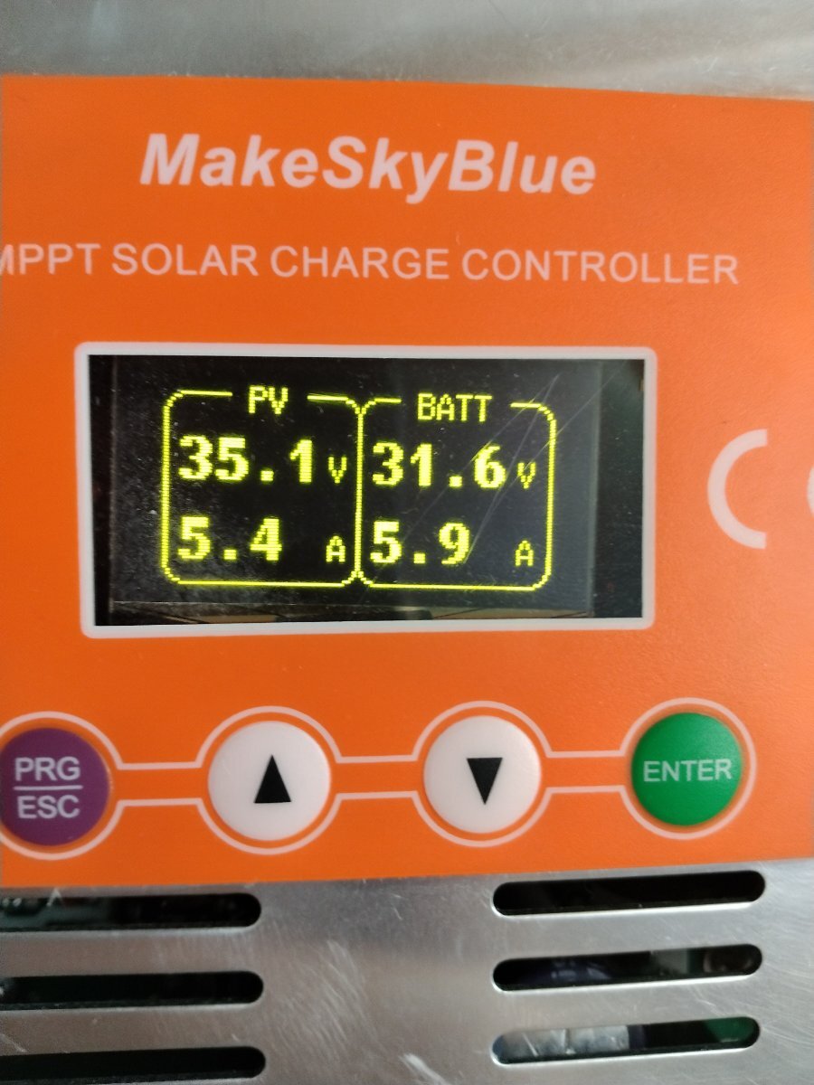
what worries me is: it looks like the current sense circuit --in the neg leg OF THE PV-- its reading PV amps.. so where do they come up with batt amps??
I have a 60A skyblue coming in in a couple days..I am gonna tear it apart and get to the bottom of this..
I have noticed something goofy going on..I have 'stacked' various configurations of panels to total various PVvoltages..the skyblue controller seems to settle at the wrong voltage point for max transfer of power..I really dont think the mppt software works..
It never really has. Prior to 118 it would often get stuck on a knee point and run the array way off MPP. There was also a condition where it would simply not MPPT at all as the sun rose in the morning and would stay with the panels near battery voltage, as if it were a PWM charger. Both would stay like that until say the panels were unplugged and reconnected to 'reset' the tracker.
118 and 119 seem to have a different algo, but it is also differently broken. Hooking up a current limited power supply to the PV input will see the charger enter a never ending cycle of ramping down to 0 watts out and back up again. This only happens in MPPT mode, ie the load can soak up all the power the charger provides. In CV mode it does seem to be stable. It seems to be unable to detect the peak. Maybe they are looking for the roll off curve at the top end that a solar panel would normally show. Regardless this is the only MPPT charger I've used that behaves like that. All the others detect Vmp of the current limited power supply and perform normally.
I have noticed the battery side voltage reading diverging under high amps out of v117 and v119 hardware so I can only guess that they arent sensing voltage at the charger's terminals, rather the far end of the PCB traces, closer to the inductors.
All up I think it'd be better to start from scratch rather than trying to retro fit better firmware into one of these things.
All up I think it'd be better to start from scratch rather than trying to retro fit better firmware into one of these things.
OK..but can u produce this amount of hardware for McDonalds-change like they are doing..??..
NO
I am now going do try and open up this hardware to open software development..not that I am some great shithead..but it looks to me that alot of people could benefit from an openSoftware interface with this msb hardware.. thats my vision..I am old..retired.. not looking for $$.. just want to make a splash to help others in the solar power world..
I will make a pcb to replace the moronic msb display and will make it available for free at osh..heat up the pcb board..suck out that rediculous nuvoton pos..1x20 ribbon cable from new display board..solder to the necessary points..
hello world.. everyone has now a platform to generate their own mppt code..
china warranty is worse than worthless, we all know that.. so lets go to work..i'll send what I have when I get there..
jack in arkansas
https://pcmp.springeropen.com/articles/10.1186/s41601-018-0111-3
The guys on The Back shed have made big strides with DIY MPPT. https://www.thebackshed.com/forum/ViewTopic.php?FID=4&TID=12027
got it HACKED!!!!
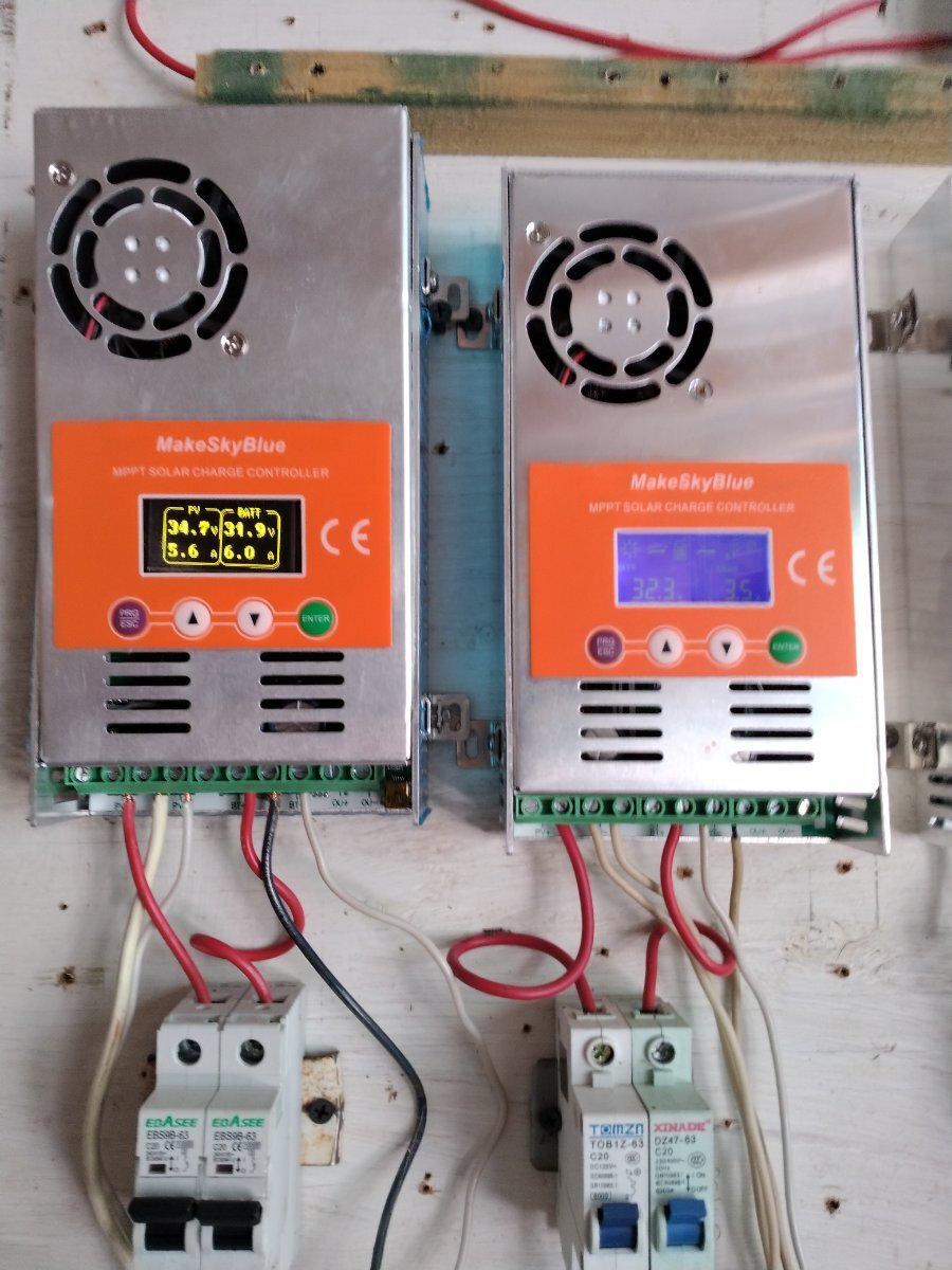
So you replaced the microcontroller on the mainboard or is this just a different display PCB? I poked around a v 117 some time ago and worked out that the comms with the LCD was i2c or spi (it was a while ago and I can't honestly remember). It was fairly trivial to monitor it with another microcontroller so I could tell what the charger was doing to automatically reset it if it got stuck on a false mppt knee or simply did not go into mppt mode at all as the sun came up.
I used a XIAO or Adafruit QT PY..same thing..and the display is a large OLED..made one pcb..the new processor is on the new display board..
I disabled the makeSkyBlue processor, didnt have to remove it.. just hold it in master RST..
had to fly a number of jumpers to the main pc board to get GND, 5v, PWMs, PV current sense amp output, fan drv, etc..
@meaculpaNice work!
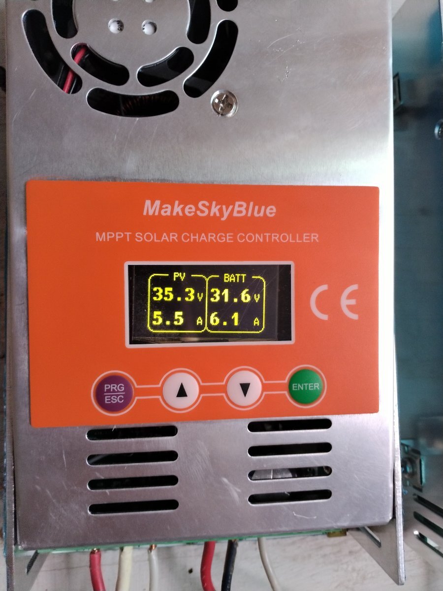
One comment: I notice the input and output voltages are almost identical (on both the hacked unit and the stock one). Are you running a very low solar panel voltage into your system? And a 36v nominal battery system?
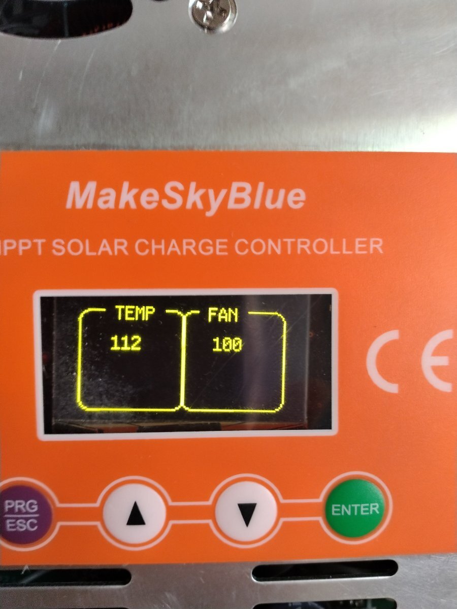
Also, the numbers shown work out to 98.3% efficiency...but the fan running full speed and 112F internally with only 3.1W of power loss...???
(I'm fully aware that anything of this sort is NOT an easy project, so probably very much a work in progress.)
I just got it going..the MPPT routine isnt real yet..I just wrote some code that more-or-less seems to work..writing a truely legit
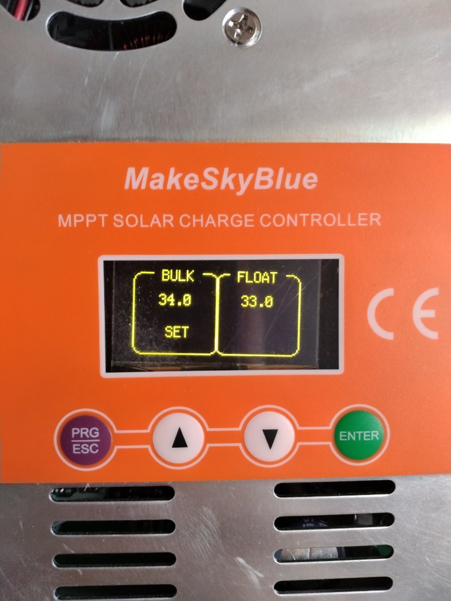
MPPT routine is going to be a lengthy ordeal (for me)..and U are correct.. my solar PV max voltage is close tp the batt voltage..not
perfect..but should still mppt a current gain..I have NiFe 100AH battery stack 20 cells..so I charge up to 33.8, float at 33.0
something nice about this makeskyblue-- actually 2 things.. one-- the power supply comes on alive first (obviously) so it requires no signals from the cpu ..regardless of ur battery voltage..as long as u meet the required minimum--12v..
and 2-- there is only one current sense.. and its in the solar pv ground leg.. this turns out to be brilliant.. battery current can then be calculated simply by wattage.. i.e. PVv x PVi = watts , therefore watts / BATTv = BATTi I should probably subtract a small amount if the fan is running, etc..
I plan on making this circuit board avalable to anyone who wants one and my code..
What frequency did their PWM run at? Did you find a way to get a half-bridge PWM output from the Xiao?
and 2-- there is only one current sense.. and its in the solar pv ground leg.. this turns out to be brilliant.. battery current can then be calculated simply by wattage.. i.e. PVv x PVi = watts , therefore watts / BATTv = BATTi I should probably subtract a small amount if the fan is running, etc..
Uhh, well, OK. I guess as long as the efficiency is known as a constant, this could be a viable means of determining output current.
the configuration of the inductors is not what u are thinking.. it is simple a step-down voltage configuration..thats why they recommend 1 1/2 to 2 times the PV voltage to the battery v..
also, the xiao in the arduino IDE has the basic freq fixed at 1khz (I suspect).. so I can even hear the inductors buzzing somewhat.. and yet I am seeing a slight current gain ALREADY.. so next I need to get down to metal and set some register to boost the freq up to 32khz or in that range..maybe find the sweet-spot the inductors like..
the two inductors are simply parallel circuits.. u can drive them individually so u could just drive one maybe to get better efficiency at low charging..