PLEASE NOTE: If you had an account with the previous forum, it has been ported to the new Genetry website!
You will need to reset the password to access the new forum. Click Log In → Forgot Password → enter your username or forum email address → click Email Reset Link.
Been watching the product progress, I wonder if there is any data logging options currently or something that may be coming.
I, too, am interested in this topic. Would also like to be able to connect from a pc if anybody figures out how to do that..
I'll probably be hacking the protocol pretty soon...have a 4-channel DSO with on-screen RS-232 sync and decode ready and waiting...just don't have an MSB with WiFi or any time to devote to it right now...
Same here its definitely in my plans, my guess snooping TX RX between the boards could substitute my own board in there to send the data to an SD card. Hoping that there is something already in the works from MSB. Just figured I would toss the idea in here.
If you have V119 charger you can tap the information via the wifi connection. I did look into it when given a V119 to evaluate but have no idea what I did with the information I gathered.
The way I did it was a bit convoluted but, connect an access point as a client to the V119 controller's wifi. Connect phone to the network behind the access point. Place a dual ethernet interface computer with wireshark running between the access point and the rest of the network and listen. It could also be done with a single interface computer and a smart switch that can reflect / mirror all traffic to a single port so that wireshark can see everything still.
For prior versions I had a microcontroller snooping the serial between the micro in the controller and the front panel. Pin 9 and 10 on the connector LCD connector on the main board IIRC.
So I've finally cracked open a v119 60A MSB charge controller, tossed the DSO 'scope probes on the TX/RX lines to the little WiFi board, installed their highly suspiciously snoopy app (how many permissions again? what, you "need" to make/receive phone calls + access device storage???!), and started writing down the decoded data. Turns out to be quite a simplistic protocol that can be read/written to pretty easily.
Data is all RS-232 @ 9600, n, 1. In the 'scope, the "master TX" line is at a 3.3v logic level ("master RX" is at 5v)...but this is almost certainly due to the ESP8266 being a 3.3v chip.
The MSB unit does not send any data unless it's first asked for data. (With no WiFi comm, the TX/RX leads are dead silent.) Checksum is the simple addition of all bytes in the packet AFTER the 0xAA header byte.
I have observed the following "master output" data packets:
- [0xAA] [0x55] [0x00 0x00 0x00] [checksum] -> "Read Status"
- MSB responds ~300mS later with the following data string
- [0xAA] [0xBB] [16: BatteryVoltage x.1] [16: BatteryAmps x.1] [16: SolarVolts x.1] [16: SolarWatts x1] [16: Temperature C x.1] [16: Cumulative KWH] [16: ???] [ModeFlags] [ErrorFlags] [0x00] [checksum]
- note: all "16" registers are 2-byte little-endian 16-bit values. For example, battery voltage bytes of [0x53] [0x01] -> 0x0153 -> 339 decimal = 33.9v
- [ModeFlags]...only seen 1 bit ever get set:
- 7:
- 6:
- 5:
- 4:
- 3:
- 2: MPPT Mode Active
- 1:
- 0:
- [ErrorFlags]...only got 2 bits set, but maybe I haven't had too many errors yet...
- 7:
- 6:
- 5:
- 4:
- 3:
- 2:
- 1: Battery Overvoltage
- 0: Battery Undervoltage
- MSB responds ~300mS later with the following data string
- [0xAA] [0xCB] [register] [0x00 0x00 0x00 0x00 0x00] [checksum] -> "Read Config Register"
- [0xAA] [0xCA] [register] [16: data x1000] [0x00 0x00 0x00] [checksum] -> "Write Config Register"
- all data in these registers seems to be multiplied by 1,000 (decimal) for whatever reason
- register 0x00 -> special case function, see below
- register 0x01 -> MPPT Bulk Voltage * 1000 (i.e. 0x48 0x71 -> 0x7148 -> 29,000 -> 29.000v
- register 0x02 -> MPPT Float Voltage * 1000
- register 0x03 -> Out Timer * 1000 (why??! 5,000 decimal = 5 hours. App won't let you do partial hours though.)
- register 0x04 -> MPPT Amps * 1000
- register 0x05 -> UVP Off Voltage * 1000
- register 0x06 -> UVP Recover Voltage * 1000
- register 0x07 -> COM Address * 1000 (pretty sure, app won't let this change)
- register 0x08 -> Battery Type * 1000 (0 = SLA, 1 = LiPo, 2 = LiLo, 3 = LiFe, 4 = LiTo--assuming, app won't accept anything other than SLA / LiPo)
- register 0x09 -> Battery Cells * 1000 (app doesn't seem to allow anything other than 2...at least for my 24v SLA battery test rig.)
- Regardless of whether function code is Read or Write, MSB responds ~150mS later with the following string:
- [0xAA] [0xDA] [register] [16: data x1000] [0x00 0x00 0x00] [checksum]
- There is one rather strange command that I don't fully understand, as it has a blank hole in place of a character. It is basically a "write config register" command to register 0x00, value 0x02.
Seems to be connected to the MPPT on/off function. Here is a 'scope screenshot:
The checksum indicates no change for the blank hole, like it's a timed delay?? 0xCC + 0x02 = 0xCE

I hope this is of some value to those who want to hack their MSB to actually get some data out of it. Pads on the PCB look to indicate that this port may have been intended as some sort of external optically isolated RS-232 interface at some point.
Reading current stats is very simple...just send the status read command, and out comes back a status string.
EDIT: Thanks to @busky for identifying the "cumulative KWH" register. Still don't know what the last "unknown is".
EDIT: more info from @busky : on/off commands (which I provided a 'scope shot of above, but apparently the "hole" in the RS-232 comms is not required!):
[0xAA] [0xCC] [0x02 0x00 0x00] [checksum] -> "MSB On"
      write_byte(0xAA);
      write_byte(0xCC);
      write_byte(0x02);
      write_byte(0x00);
      write_byte(0x00);
      write_byte(0xCE);
MSB responds with:
0xaa, 0xdd, 0x0, 0x0, 0x0, 0xdd
[0xAA] [0xCC] [0x01 0x02 0x00] [checksum] -> "MSB Off"
      write_byte(0xAA);
      write_byte(0xCC);
      write_byte(0x01);
      write_byte(0x02);
      write_byte(0x00);
      write_byte(0xCF);
MSB responds with:
0xaa, 0xdd, 0x1, 0x0, 0x0, 0xde
Note that the last byte of the MSB response is always the checksum byte--calculated INCLUDING the 2nd byte!
(When "off" the ModeFlags are 0x00.)
Thanks well don't have one where I am at right now but going to have to try it out wonder if the non wifi model has those data pins. Thanks for posting it. Good capture for future people coming to the forum too.
1 minute ago, AquaticsLive said:Thanks well don't have one where I am at right now but going to have to try it out wonder if the non wifi model has those data pins. Thanks for posting it. Good capture for future people coming to the forum too.
So there is a minor difference between WiFi modules and non/WiFi modules...maybe. The one unit I had (and eventually gave away) that didn't have WiFi...doesn't have the header that this one does. But the same pins are sorta there.
Here's a photo I took of a non-WiFi MSB MPPT, and then super-imposed parts onto that I presume were originally intended for an optoisolated RS-232 port:
<fileStore.core_Attachment>/monthly_2021_05/image.png.df496dda919d0d0a01bc61741671e5fc.png
Interestingly the power pins provided are different here; it's 3.3v for the non-WiFi unit, but 5v on the WiFi enabled unit. Maybe the comm protocol is the same?? I haven't a clue. Also noting there's another RX/TX port on the top left of the board closer to the MCU.
Here's a schematic of how I think the isolated circuit would work....
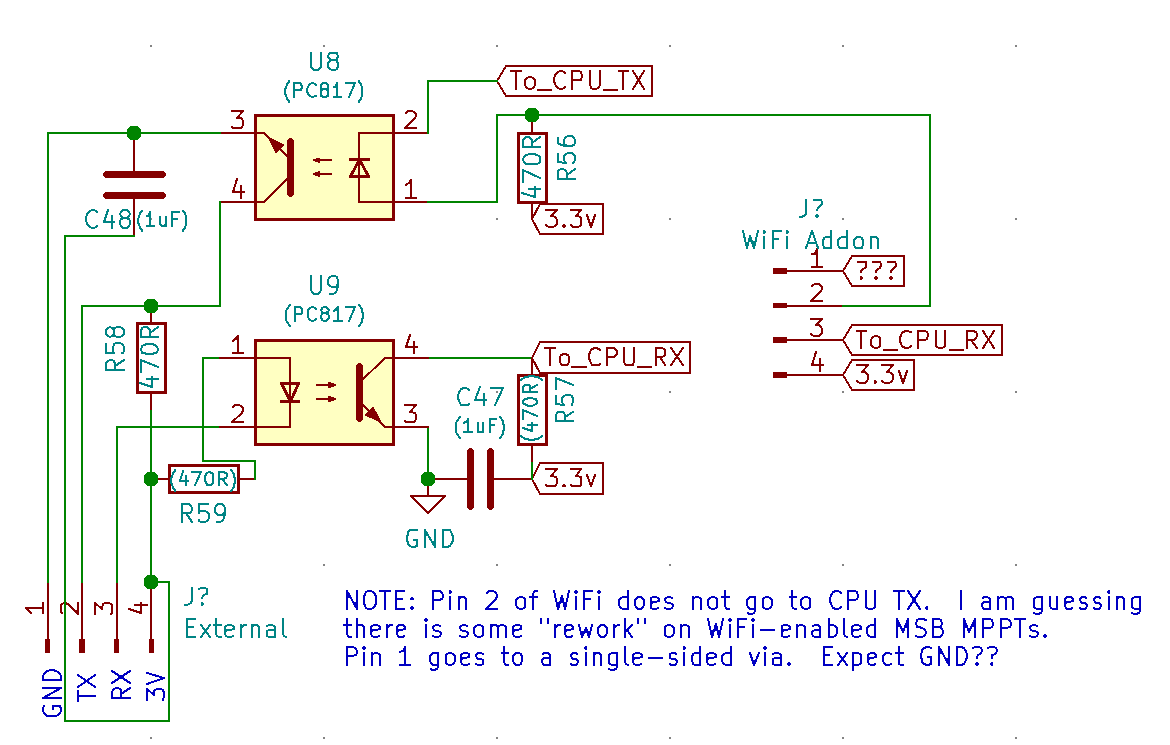
Obviously, completely up to the end user....
Found by accident that I can read config registers past register 0x09 that the app uses. Not sure if this is a memory leak or some "hidden" settings...
The WiFi-enabled units have a 4-pin header soldered to the board BEFORE where the optoisolators could go, and they also provide 5v power, not 3.3v. So...a few differences I suppose!
Didn't think of it until now, so thanks for the inspiration everyone, but I have some V117 hardware with V118 firmware loaded. It's been a while since I looked inside the V117 but I think there is a serial port header near the terminal block, but with no components populated at all. I'll try sending some serial commands on the lines going to the microcontroller, you never know, V118 may be listening.
The serial lines are active low, which makes TX/RX very easy to differentiate.
One option is to follow the lines all the way back to the MCU; it was fairly easy to work out from the datasheet which pins went to the UART (RS-232) modules.
The other option would be to try to find the 2 lines that go all the way from the MCU, to the pads for the optoisolators. As these are both active-low, the TX line will be at ~5v, while the RX line will be floating at 0v.
PLEASE NOTE: These are TTL 5v logic level signals. If you want to connect these to a computer RS-232 port (or a level-shifted USB->RS-232 converter), you will need a RS-232 level shifter (MAX232, SP3232, etc.)
I am thinking of using one of those DFRobot multi converter boards has multiple inputs and outputs types so I can adapt to my existing RS485 network of devices. Well just brain storming a bit but will need to come back to this when I have some time to tinker more.
I am thinking of using one of those DFRobot multi converter boards has multiple inputs and outputs types so I can adapt to my existing RS485 network of devices. Well just brain storming a bit but will need to come back to this when I have some time to tinker more.
It could be adapted to an RS-485 "network" if you use an auto-direction RS-485 driver like the MAX13487 (look for modules on eBay by searching for "MAX1348"...they work pretty good).
No response with v118. Oh well, at least snooping on the LCD is still possible but nowhere near as convenient.
Did you trace the 2 wires back to the Novatel MCU's serial port leads, and verify 3.3v / 5v on the "TX" lead, and 0v on the "RX" lead?
Seems I found a hint that the v119 is for the "WiFi" module type, and v118 isn't. But they still have 2 separate serial ports broken out on the PCB...