PLEASE NOTE: If you had an account with the previous forum, it has been ported to the new Genetry website!
You will need to reset the password to access the new forum. Click Log In → Forgot Password → enter your username or forum email address → click Email Reset Link.

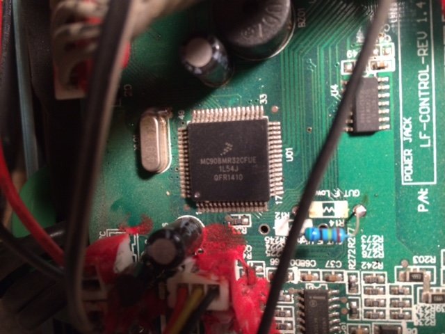
Forgot to send the pic of the cpu. Tried to get a readable pic. Sorry, I'm not a great photographer.
3 hours ago, dochubert said:
That is back in the stone age. No wonder it still runs. Version 1.4. 🙂
Wow, thanks a lot for the photos. I guess I still don't know when they switched to the Microchip PIC, but that's a Freescale/Motorola 68HC08-based processor. I see they had a fan rotation sensor on that design; that was the case on some older PJ inverters with the current Microchip PIC CPU.
Amuses me how much this v1.4 board almost literally mirrors the control board design on a 15kw Yiyen that I've seen photos of...like there isn't an original Chinese inverter design 😉
I have so many questions already...especially considering that this one has been so reliable. Maybe someday this year we'll trade it for a GS inverter so I can get a closer look at it. I mean, don't get me wrong, we aren't going to switch to their design--the GS design seems to work very well--but curiosity killed the cat, and I can't get past it 🤣.
Also curious what the (2) 14-pin ICs near the CPU are? One of my many pet peeves on the current PJ control boards is the quad NAND gate (HEF4011BT) that's used to turn on 4 transistors to short the PIC's SPWM outputs to zero "if there is fault." Not like the PIC itself has a "FAULT" input that can be used to instantly shut down the SPWM outputs--AND notify the CPU...
I see "LF DRIVER v1.1" in the bottom right hand corner of the control board; I'm curious what the socketed ICs are? Also maybe a closeup of the LF Driver area? Looks like they covered a lot of the parts in goop...don't damage your inverter trying to remove it.
Yeah, the FETs are all directly soldered into the board, but amongst the (precision) resistors (haha, really?) there's some other more square parts...cap? diode?
Jack probably looks at our GS control board and says, "That's where we started, stupid Americans." But hey, if this relic just won't quit, maybe there's something to it!
Glanced at a datasheet for that processor. Goodness gracious, it barely has anything! Good for them it at least has an PWMMC (PWM motor control) module with up to 6 PWM outputs / 3-phase capable drive. Doesn't even have an RS-232 driver. Just 2 timers. 768 bytes of RAM.
I'm glad they switched to the Microchip PIC--that thing has heaps of memory and features (by comparison).
I see they had a fan rotation sensor on that design
Something the Australian forum figured out early on was that you had to have the fan plugged in or the inverter wouldn't run.
I see "LF DRIVER v1.1" in the bottom right hand corner of the control board; I'm curious what the socketed ICs are?
The sockets were at first added by users to make rebuilding driver boards easier. You couldn't easily buy new boards back then. As is their reputation, PJ hit and miss put sockets on some but not others. I remember I destroyed a driver board trying to remove those optos from a soldered board.
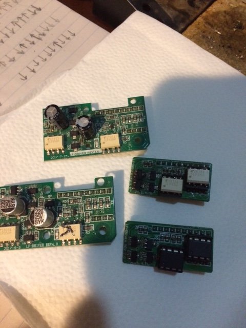
I'd get a better pic of that v1.1 lf board but already put the cover back on and put the inverter back to work. Most lf boards from v2.0 on used the standard TLP350 ics, but I think the v1.1 black ones are the same as these in a v2 lf board; see pics. I've got a couple more lf boards somewhere. If there's any different when I find them I'll send you pics.
If you want one I will send you one of my v2.2 control boards. Probably too flaky to run an inverter, but might provide some info for your research. It has what appears to be the same two ICs you were wondering about near the cpu. Email me an address if interested.
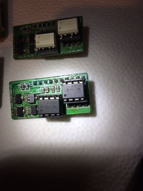
Nice, thanks for the photos. Ha, the LF Driver board used to be pretty small ;-). Still uses the exact same concept today as it did back then...the "A3120" is an HCPL-3120, which is almost the same as the TLP350 in the other boards (and still used today). The transistors serving as totem pole drivers haven't changed since day 1 it seems.
Funny they socketed the optocouplers...those aren't usually what burn out. Usually the totem-pole transistors that go poof...
No need to open up your trusty inverter again...I see that the "black chips" on the LF Driver are really the same thing as they use today, just a different part number. Solves that question for me.
@dochubert Is there any way you can measure the SPWM frequency of this v1.4 PJ inverter? Based on how limited the processor is, I wouldn't be the slightest bit surprised if it's running a much lower SPWM frequency--which would immensely help the FETs with the undersized drivers.
If you have a 'scope, you can put it across the FET heatsinks where the transformer connects, and figure out the frequency that way. (A fancy DMM with frequency readout might possibly suffice.) Newer inverters run 24KHz @ 60Hz. I wouldn't be surprised if this one runs half that...
Failing either of those methods, if you can hear a very high pitched squeal from the inverter when it's on--that'd be a dead giveaway. (Of course, high frequency hearing is one of the first things that goes in the human experience, so this might not work either!)
Ok, I have a dmm that does frequency I use to display the sine wave output of my inverters. Should work.
If I'm going to open the inverter up again, is there anything else you want me to do while there? (better pic of the lf board)
If I'm going to open the inverter up again, is there anything else you want me to do while there? (better pic of the lf board)
Not really. The photos of the other LF Drivers showed me pretty much what I wanted to know.
Tested a GS inverter with my DMM on frequency...I know that the switching frequency is 24KHz, but the meter read anything but that. Best readings were with one probe touching a FET heatsink, and the other in the air--it varied between 22-26KHz. With the probes across both heatsinks, I got ~14.5KHz...not quite half of the actual output.
Maybe it's just not worth bothering with...
Out of an ASL1? I severely doubt it. The ASL1 core is so small, I don't think it's possible to get enough wire around it to handle 3kw total load.
Well If I had a better setup right now with a filter capacitor on the L2 side I'd try it. I do know that the ASL1 can handle 1K on L1 without any problems. I was pushing it to over 2K on only L1 this morning. It did kick out at about 2100 Watts after about 10 Minutes. When I dropped back to 1200 Watts on L1 it had no problems at all. So if balanced between L1 and L2 it might have no problem with 3kW. Video proof is at