PLEASE NOTE: If you had an account with the previous forum, it has been ported to the new Genetry website!
You will need to reset the password to access the new forum. Click Log In → Forgot Password → enter your username or forum email address → click Email Reset Link.
The only thing I can come up with is a linear regulator and a total LV side draw around 1A. 24 Vbatt, 5W to the circuitry, 15W to heating up the air. That would also explain the increased idle draw for higher batt voltage models. At nom 48V, about 50W dissipated, 5 to the load, 45 to heating up the air. I can't see a regulator with sufficient heatsinking in the pictures of the ones I've seen though. It might also be that they use a bypass resistor to provide must of the current with a linear regulator supplying the remainder to keep regulation. If there is a chunky power resistor on the board that would be a likely candidate.
Very fair assumption, it'd make a lot of sense.
However, ALL of the LF Chinese inverter control boards I've seen (covered on another thread) use the EXACT same switching transformer-based power supply for the +12v supply (same as PJ, mind you). The transformer has 4 secondaries: 2 for the high-side FET drive supply, 1 for "main 12v", and another for negative voltage (used for the op-amps.) But PJ puts a heatsink on the drive FET, indicating significant losses there, so........
...though it seems the older PJ designs used a zener diode across the 2 high-side FET drive supplies to limit the voltage (said zener diodes simply nonpopulated on the current boards). If the little transformer is pretty lossy, that'd explain a decent amount of loss--but not more than 2-3W (because said diodes can't dissipate more than that!)
It'd be interesting to see what a thermal camera shows. Those watts have to be going somewhere. Unless it's a lot of somewheres 15W is going to make that thing quite toasty. Exceedingly poor design for the LV switching supply? I guess they could have ultra bad drive for the FET (presumably they use a FET there) and it's running in the linear region instead of hard on / off? Losses in that transistor, the switching transformer, slow rectifier diodes, the clamp diodes on the FET drive supplies. I guess they might actually get to 20W if they tried hard. An achievement of a type, but not something to admit to!
Exceedingly poor design for the LV switching supply? I guess they could have ultra bad drive for the FET (presumably they use a FET there) and it's running in the linear region instead of hard on / off? Losses in that transistor, the switching transformer, slow rectifier diodes, the clamp diodes on the FET drive supplies.
That's highly possible--PJ uses an IRF630 (9A) or IRF640 (18A), directly driven by a UC2843. I don't see why the FET should need a heatsink, unless something's really wonky with the drive.
I guess they might actually get to 20W if they tried hard. An achievement of a type, but not something to admit to!
Hehe, agreed 😉.
I know people love to slag off the powerjack/upower inverters (often quite rightly so!) but my experience has not been so bad.
My first foray into off-grid power started in 2018 when I obtained from a friend's deceased relative a 2013 PJ 8k 24v-230v inverter (not split phase). Inside it had a V3 (I think) control board, two AS2 ( I think) transformers in series, and a few modifications including 45C thermoswitches bolted to the FET heatsinks to operate the fans, and a manual fan override switch. This inverter is still working today although no matter what chokes I have tried it still draws about 2.5A (~50W) at idle. The inverter function worked well but the charging function went wookie unless the fans were running. I discussed this in another post... I've since changed the fan override switch to run fans at about half-speed until the thermoswitches turn them to full power. This unit produces a very clean sine wave output all the way up to at least 3.6kW before the overload LED comes on. I've not ran it at this power for more than 20 mins and not tried to go above this as it meets my needs and as it has survived 8 years already I don't want to blow it up for the sake of testing loads which I will never run it at. I used it throughout this summer but the idle consumption is an issue during winter here where there is little sun.
Shortly after this I obtained a 'ProMariner' branded 2kW PS unit. This was insufficient for our needs and although I didn't have an oscilloscope at the time it was noticeably weaker than the powerjack e.g. the microwave would take longer to cook stuff than when running on the PJ.
In November 2020 I bought a secondhand Victron 3k unit. I wasn't sure of the exact age but it worked perfectly for about 2 weeks after I bought it. It never got loaded much above 2.5kW, and all the cooling fans were working so I am not sure why it failed but it did fail. It started of by intermittently refusing to power up the output stage, giving an 'overload' LED even when there was no load, until a day or two later going straight to 'overload' without even powering up the output stage. I tested the transformers and FETs and they were fine, so I concluded the fault was on the control board. The control board was very complex and antiquated looking with a lot of ancient DIL logic IC's and a lot of very neatly wired, probably factory rework on the back of the board. I contacted Victron but they just said the unit was obsolete and there were no spares or support for it.
So as by now although the old PJ still worked, I still wanted a newer and more efficient inverter, In January 2021, I bought a 'upower' 8kW unit, knowing that at best it would do 3.6kW like the ancient PJ. This had rev 10.3c boards but was slightly lighter in weight than the old PJ 8k as it has a single ASL3 transformer rather than the two AS2 transformers of the old unit. I observed on the scope significant flattening of the sine wave peaks with loads above about 1.5kW but it still tolerated loads of 3.6kW for 20 mins without any alarms or shutdowns. But when spring came I put it aside and resumed using the old 2013 PJ. Recently by removing one turn from the primary windings I have reduced the severity of the flattened peaks, but they are still there. However I can tolerate this during winter as it draws only 0.9A at idle instead of the 2.5A of the old PJ and the difference in 'real world' performance e.g. cooking, washing machine, etc. compared to the older PJ is negligible. As with all my inverters, it gets swiched off during night for the 7 hours where we have cheap-rate grid power (called Economy7 in the UK).
Having since learned about the GS units I would have opted to buy one of those but as they don't ship overseas due to complexities of customs paperwork, cost, etc, PJ/upower units are the best performance per buck that we can get in the UK. I have been lucky, but as has been said many times on this forum it can be pot-luck what you get with these chinese vendors.
As a semi-competent electrical engineer, I bought a complete set of PJ boards (11.1) and using formulae available on other forums wound my own transformer on a 52cm2 toroid core. This gave a near-perfect sine wave up to 3.6kW and the transformer barely got warm even after 20 minutes with no cooling fans (the fans only cooled the main+control boards). However like the old PJ it drew a stubborn 2.5A at idle. I tried two full turns on the late PJ/upower ferrite rings as well as other choke configurations but it was either the same or worse idle consumption. In the end I found the best chokes were some random E-I chokes I recovered from a decommissioned 48v rectifier. One choke would have been sufficient as the copper strip they were wound with was perfectly capable of 150A+ without getting hot. But the lead-in cables were only 13mm2 so these got hot. It was impossibble to replace the lead-ins without destroying the chokes. Therefore I had to put two in parallel. With fan cooling these remain at acceptable temperature with sustained 3.6kW load. And the idle current is about 1A (25w) which is also acceptable. I have the housing for this project but just haven't got around to it yet!
6 hours ago, Paul said:My first foray into off-grid power started in 2018 when I obtained from a friend's deceased relative a 2013 PJ 8k 24v-230v inverter (not split phase). Inside it had a V3 (I think) control board, two AS2 ( I think) transformers in series, and a few modifications including 45C thermoswitches bolted to the FET heatsinks to operate the fans, and a manual fan override switch. This inverter is still working today although no matter what chokes I have tried it still draws about 2.5A (~50W) at idle.
From what I've heard, the older PJ inverters (< v5 for sure) were very reliable. Also IIRC they don't use a Microchip PIC MCU...indicating a different firmware.
While the control board circuitry on the latest PJ designs is definitely problematic, I am actually pretty sure that a lot of the "charging" woes on the latest PJ inverters is due to firmware issues. The core control board design concept really hasn't changed much from v2 all the way through v11...just there's been a lot of added "fluff" that is really just Band-Aids around firmware issues.

20 hours ago, Sid Genetry Solar said:From what I've heard, the older PJ inverters (< v5 for sure) were very reliable
The Version 3.4 powerjack control board seems to be the best one. If someone were to copy that design without 'improving' it, they would have me as a customer for at least two of them. Probably more. I can't be the only owner of older powerjack inverters who would happily pay a reasonable price for a truly reliable control board that would restore those inverters to working order (without having to 'update' them).
Since powerjack copied the design from someone else, shouldn't be any legal issues. If it is a concern, adding a potentiometer to allow output voltage adjustment, which the v3.4 didn't have, would change it enough to avoid that concern. And/or just completely eliminate the charging function, leaving off all of the parts related to charging, making it simpler and cheaper to produce. More powerjacks have likely been blown by people trying to charge batteries than by all other reasons combined. Serious solar power producers don't use the charging functions anyway. That's what solar panels are for!
(I know. I said I didn't want it improved. Then I went ahead and suggested two or three improvements. Guess I'm no better than the other guys.)
The Version 3.4 powerjack control board seems to be the best one. If someone were to copy that design without 'improving' it, they would have me as a customer for at least two of them. Probably more. I can't be the only owner of older powerjack inverters who would happily pay a reasonable price for a truly reliable control board that would restore those inverters to working order (without having to 'update' them).
The only significant difference on the FET drive between a GS controller and a PJ inverter...is that one's perfectly balanced and more than strong enough--and the other one isn't. Yes, the PJ inverters use a floating high side drive method...but that does not figure into the actual performance.
I can technically make a very imbalanced and weak driver for a GS inverter to approximate the same effect...
You don't have to go very far to find a "copy" of the older PJ board design: pretty much ALL of the cheap Chinese LF inverters use pretty the exact same PCB.
They also don't have very high reliability marks.
More powerjacks have likely been blown by people trying to charge batteries than by all other reasons combined.
This likely has to do with the CPU firmware first and foremost, with the AC input handling being second (i.e. split-phase AC backfeed due to the inverter only disconnecting L1.) A distant third would be the weak FET drive control (i.e. crosstalk / EMI weak-triggering FETs, etc.)
Sid, you are a much better tech than I could ever pretend to be, so I can't argue with your statements. All I can do is assert that an older powerjack with a version 3.4 control will run strong with clean output and reliably for years, while that same powerjack 'updated' to newer controls will run much weaker (poorer sine wave over voltage range and lower power handling capability) and generally fail in a much shorter time.
Does it make sense? I can't explain it. But it is an observation, not wishfull thinking. The wishfull thinking comes when I wish for a few more v3.4 control boards.
All I can do is assert that an older powerjack with a version 3.4 control will run strong with clean output and reliably for years
No question there. I personally believe the "clean output" has a lot more to do with the transformer ratio, than the control board--as on the newer inverters PJ tends to run higher and higher transformer voltage specs. This causes them to "flat-top" sooner--but according to PJ, it reduces the number of inverters that blow up
while that same powerjack 'updated' to newer controls will run much weaker (poorer sine wave over voltage range and lower power handling capability) and generally fail in a much shorter time.
Wouldn't be surprised if this has to do with not only FET resistors / FET choices, but also the added "garbage" between the CPU and the driver board in the more recent versions.
Worth noting: I personally was astounded when testing the first GS boards (and even to this day). Take a PJ inverter: the transformer has a very definite hum/buzz that we're all very familiar with. (The newer ones have a double hum...the 60Hz hum with a 30Hz regulator oscillation superimposed on it, which causes flickering in sensitive lights.)
With a perfectly balanced/matched GS driver, etc., etc. the transformer will be almost DEAD SILENT. To the effect of, "Well, I turned the inverter on, but it evidently isn't working." Then put a meter on the output and, "Whoops, wait a minute, it IS running!"
Not to mention the 12kw GS inverter when running at high load...the transformer is getting hot and all, but the FETs were basically room temperature at 10kw (obviously, this was with a single high-speed fan blowing through the heatsinks).
Maybe I'll be able to work something out to get you a GS setup just so you can see how much of a difference it makes. Not like I don't have repaired/reject parts around that I can't pull something together that otherwise would just sit around...
On 11/7/2021 at 12:36 AM, Sid Genetry Solar said:From what I've heard, the older PJ inverters (< v5 for sure) were very reliable. Also IIRC they don't use a Microchip PIC MCU...indicating a different firmware.
While the control board circuitry on the latest PJ designs is definitely problematic, I am actually pretty sure that a lot of the "charging" woes on the latest PJ inverters is due to firmware issues. The core control board design concept really hasn't changed much from v2 all the way through v11...just there's been a lot of added "fluff" that is really just Band-Aids around firmware issues.
I double checked my old PJ yesterday. In my mind I had thought it was a v3.x but actually it is a v1.2/v1.4 depending on which of the silkscreen prints you believe! Still working perfectly as an inverter although the charge function can be a bit flaky as mentioned in a previous post (I don't use that feature anyway).
<a href="/monthly_2021_11/20211108_175816.jpg.d32b14900669db8b53a0128f36b5a8c8.jpg" class="ipsAttachLink ipsAttachLink_image"><img data-fileid="858" src="//forums.genetrysolar.com/applications/core/interface/js/spacer.png" data-src="/monthly_2021_11/20211108_175816.thumb.jpg.fc17064d072ad8685f84849443788c5c.jpg" data-ratio="75" width="1000" class="ipsImage ipsImage_thumbnailed" alt="20211108_175816.jpg">
<a href="/monthly_2021_11/20211108_175808.jpg.9576c93369cd71eb8ba14315d42715a7.jpg" class="ipsAttachLink ipsAttachLink_image"><img data-fileid="859" src="//forums.genetrysolar.com/applications/core/interface/js/spacer.png" data-src="/monthly_2021_11/20211108_175808.thumb.jpg.5fcd02cd45dcca1d6ba9087ae941925d.jpg" data-ratio="75" width="1000" class="ipsImage ipsImage_thumbnailed" alt="20211108_175808.jpg">
2 hours ago, Paul said:I double checked my old PJ yesterday. In my mind I had thought it was a v3.x but actually it is a v1.2/v1.4 depending on which of the silkscreen prints you believe! Still working perfectly as an inverter although the charge function can be a bit flaky as mentioned in a previous post (I don't use that feature anyway).
Could you upload a photo of the entire control board? Just for curiosity's sake I guess 😉
Could you upload a photo of the entire control board? Just for curiosity's sake I guess 😉
Sure. Here it is. sorry some of it is obscured by wires etc. But i'm reluctant to pull all the cables out of such an ancient working inverter to get better picture.
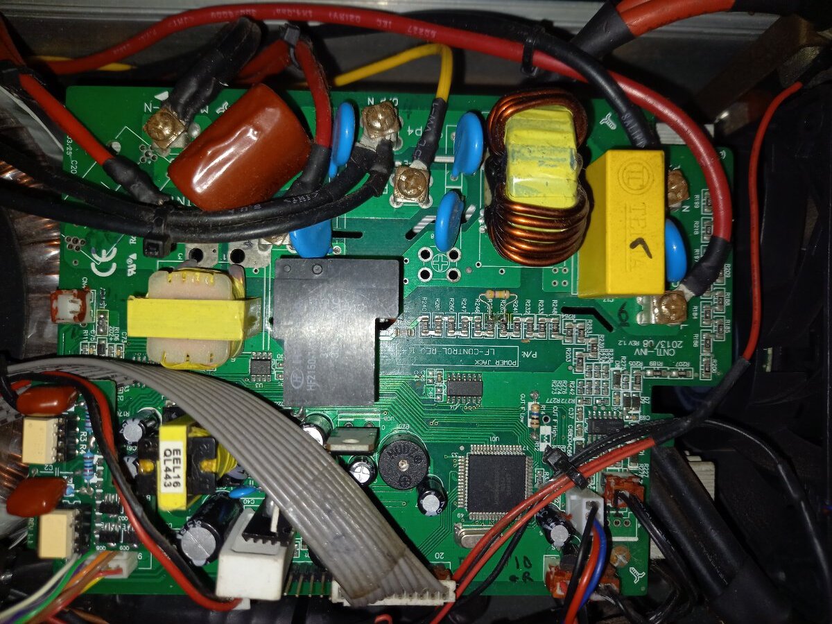
Ha, now I see the "v1.2" at one spot and "v1.4" at another spot on the same board...
Looks like a pretty typical "Chinese LF inverter" design; I do notice that the MCU ("CPU") is not a Microchip product. Different codebase...wonder if that has more to do with the inverters' blowing up than the PCB design...
7 hours ago, Sid Genetry Solar said:Ha, now I see the "v1.2" at one spot and "v1.4" at another spot on the same board...
Looks like a pretty typical "Chinese LF inverter" design; I do notice that the MCU ("CPU") is not a Microchip product. Different codebase...wonder if that has more to do with the inverters' blowing up than the PCB design...
Probably like you say the crap firmware on the later MCUs is what causes them to blow up. I'll try to get some close up pictures of the MCU and FETs to see what they were actually using at this time, as I'm also curious. This one doesn't even exhibit the intermittent 25/30Hz output voltage oscillation that the v10/11 boards do. Also I note that the FET drive ribbon cable is very short on this unit - less than 10cm. So that would also improve the FET drive signals compared to the later units which seem to vary from 15 to 30cm long!
Overall it has been a better performing and more reliable inverter than any of the other units I have used - even the Victron Phoenix 24/3000. The only negative point that I have found is the high idle power (~70w).