PLEASE NOTE: If you had an account with the previous forum, it has been ported to the new Genetry website!
You will need to reset the password to access the new forum. Click Log In → Forgot Password → enter your username or forum email address → click Email Reset Link.
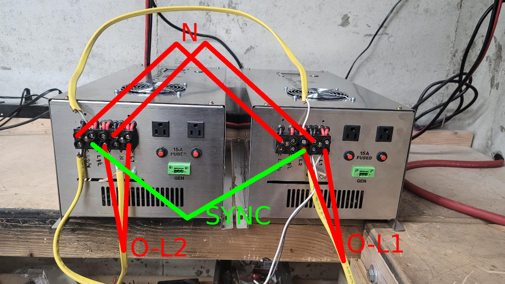
On 5/19/2021 at 12:01 PM, Sid Genetry Solar said://content.invisioncic.com/g308908/monthly_2021_05/image.thumb.png.29bff83aea7a6e14fb33489adedd41cd.png
Here's the best I have for that. Notice that there are 2 "L" and 2 "N" outputs for each inverter, this paralleling is necessary for the 50A total at max load. Wires are rated for the 25A max load @ 240v, so when we go to single-phase, the full output load at 120v is 50A.
Sync wire is the green one; that provides the "sync" signal to the slave inverter to follow. The unused terminal on the "master" inverter is the 120vAC input.
EDIT: Just realized this is an older photo without the stickers. Master inverter is on the right, slave inverter is on the left.
So, if there is no connection to Neutral on the control board, what's function does the wire connecting N to N on the Output block serve?
In my confusion, I see this connection doing nothing since the wire inside the inverter is not connected to anything???
I believe the so-called neutral to neutral is actually leg-to-leg (neutral is such a quirky concept), effectively making it the center-tap between two transformers - without it, you would not be able to get 240v between the two inverters. (Since each inverter is only putting out 120v) In laymen's, it's how the inverters are connected in series.
Remove the jumper between the transformers and you'll notice the 240v lamp will not receive power. Worth mentioning that this is effectively a mandatory thing to do, as the jump will happen in your panel when you connect each inverter to the neutral line for your house - there's no way to hook both inverters to your panel without this jump happening.