PLEASE NOTE: If you had an account with the previous forum, it has been ported to the new Genetry website!
You will need to reset the password to access the new forum. Click Log In → Forgot Password → enter your username or forum email address → click Email Reset Link.
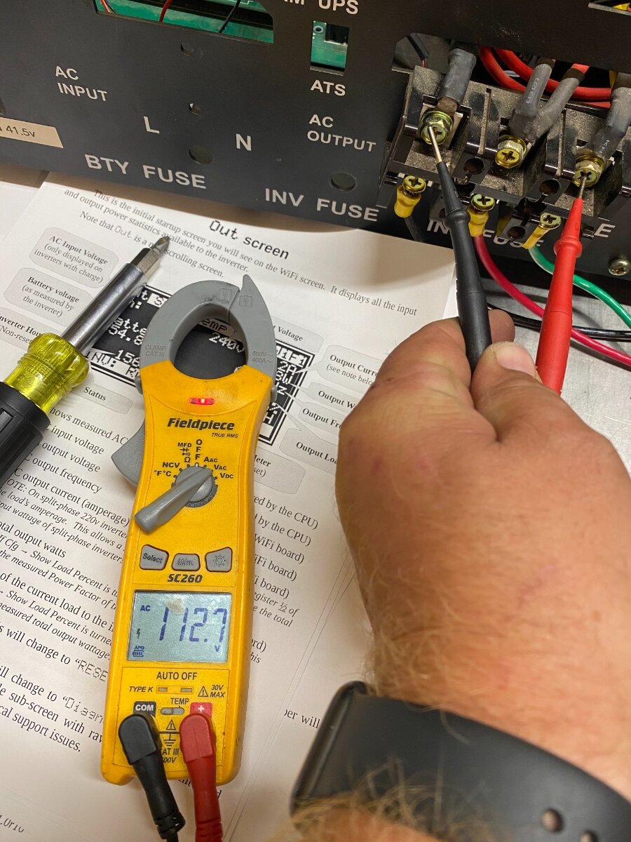
So I hooked up my mancave tiny house to the inverter I been working on finally, I have a load on it: led lights & a Milwaukee battery on a charger charging but not getting any readings on display??? I believe I ran the wires going opposite ways on the hall sensor. I’m stumped atm. Pictures for ideas on my issue.
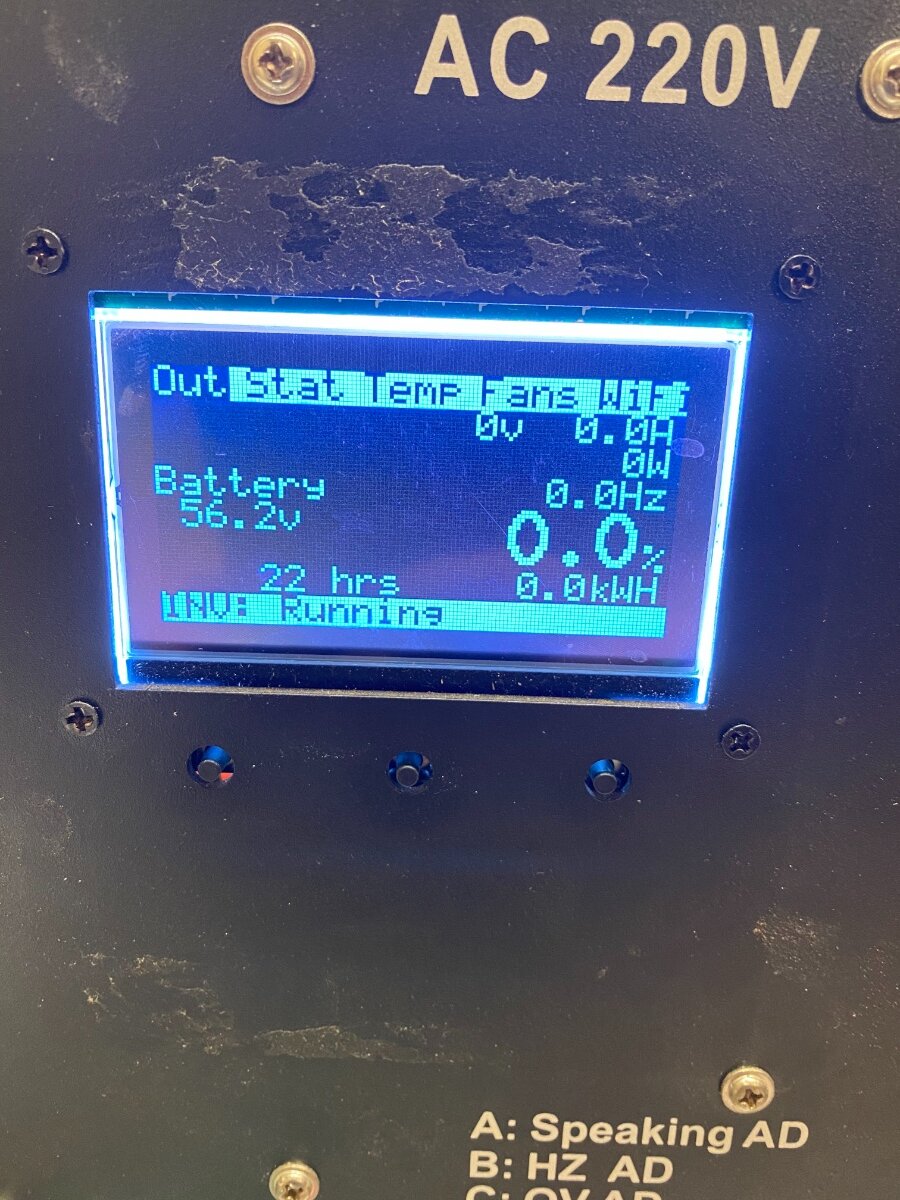
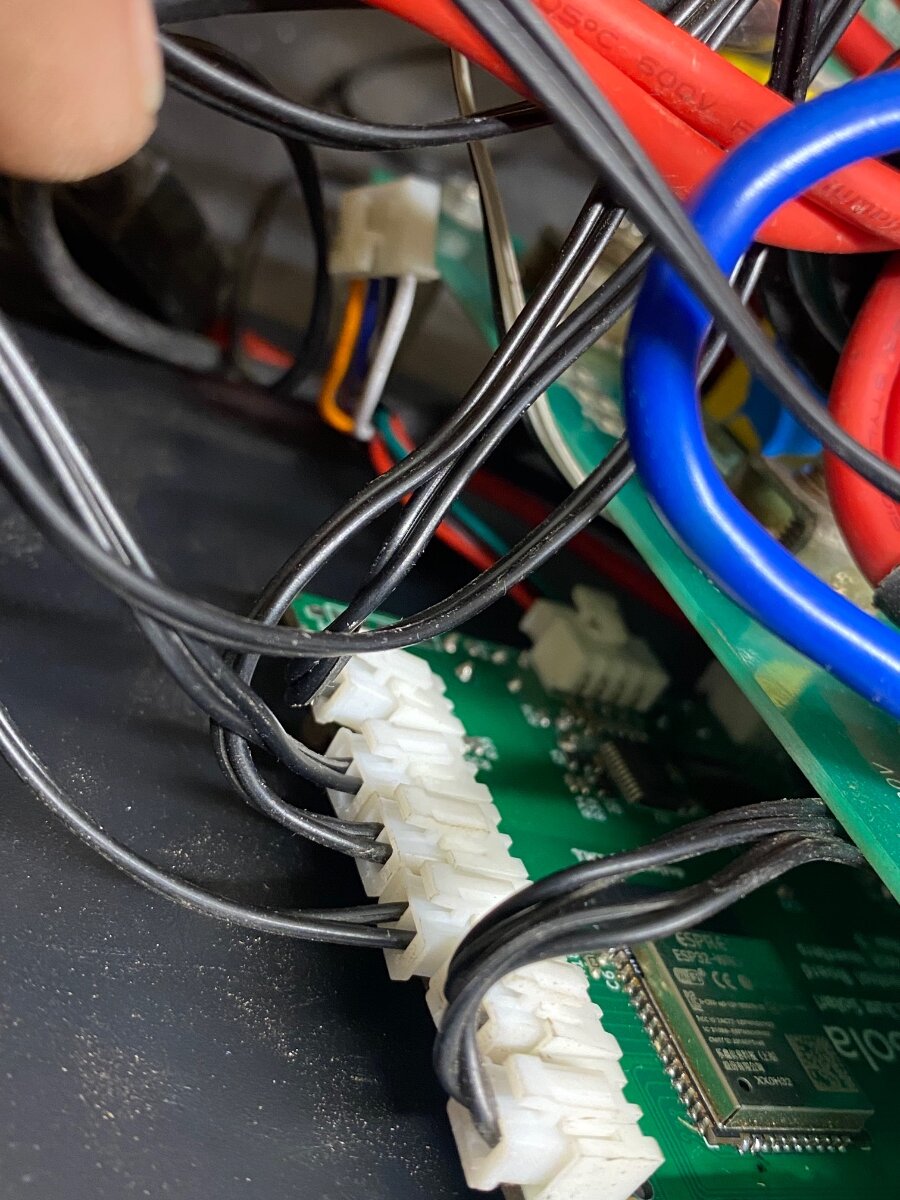
I see the problem. There's no cable going from the PJ "output" board to the WiFi board's FDBK connector, so it has no voltage or current feedback. (Will note on a GS Rev. C setup, the feedback cable is deprecated--but on a PJ setup, it's required.)
This cable should be the same as went to the original LCD.
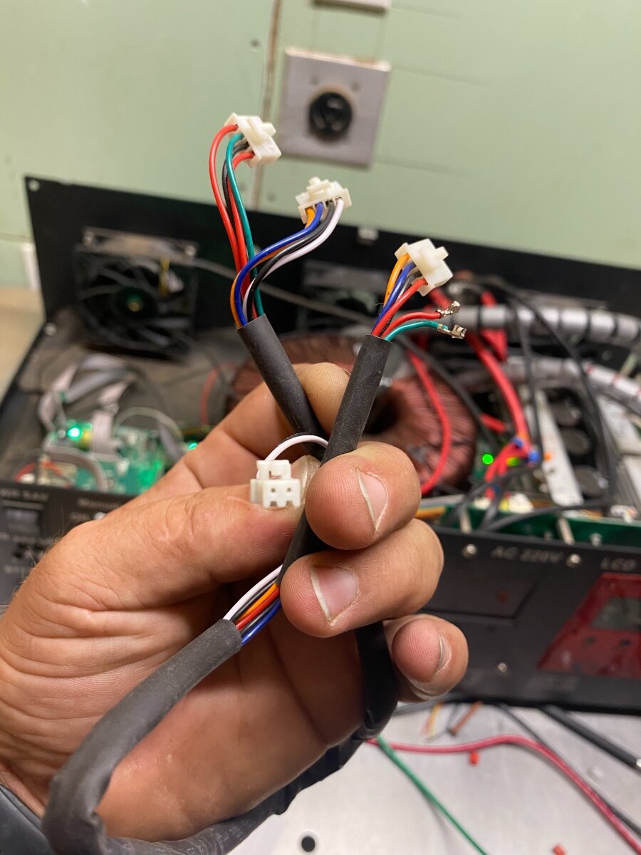
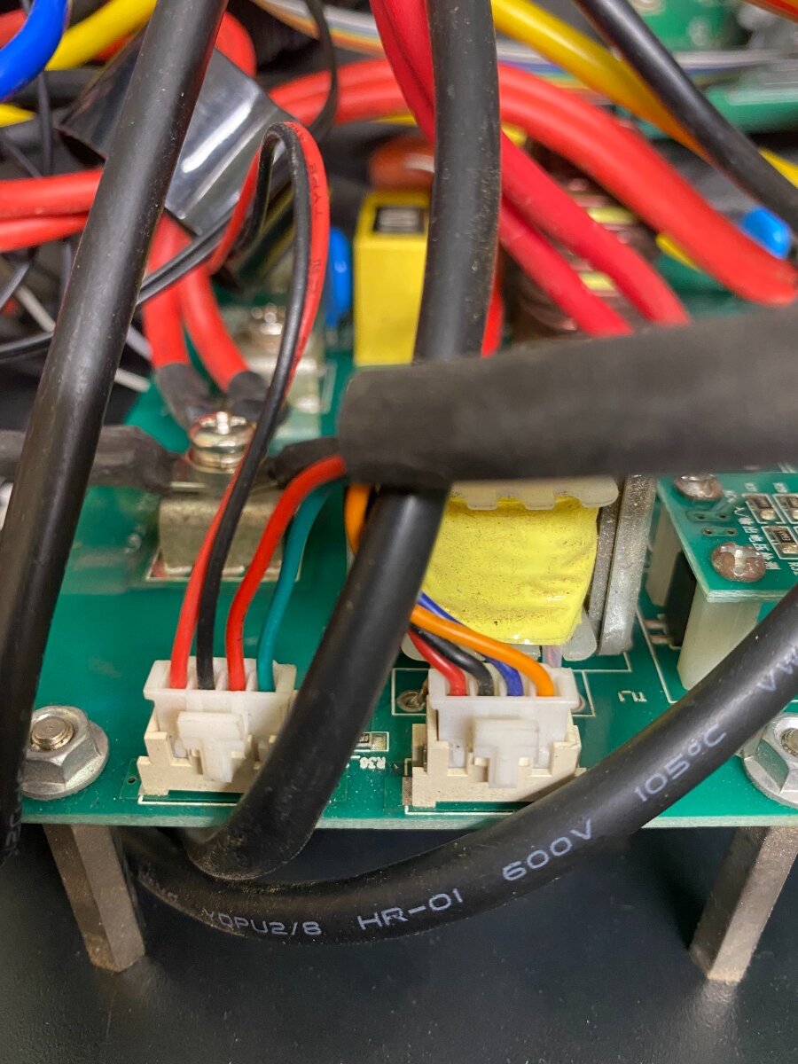
WARNING: Make sure you differentiate between the 2 different 4-pin cables on the v9 and newer cable!
One 4-pin connector has (among other colors) orange and blue. DO NOT CONNECT THIS ONE TO THE WIFI BOARD! It has 12v, which will damage the power monitor chip if plugged into the FDBK connector on the WiFi board.
The other 4-pin connector usually has red, black, red, green (or some combination of that.) This is the one that needs to be plugged into FDBK on the bottom of the WiFi board.
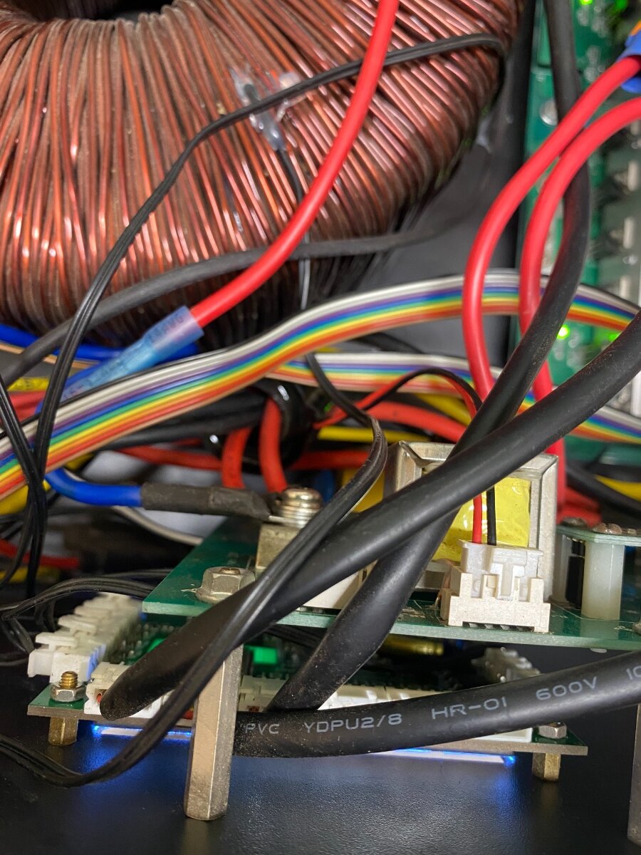
...if I'm not mistaken in the photos, the original PJ LCD cable has been completely taken apart??? If so, we'll have to put at least part of it back together.
...if I'm not mistaken in the photos, the original PJ LCD cable has been completely taken apart??? If so, we'll have to put at least part of it back together.
Ooo so this one? I’m not sure why I depinned the connector
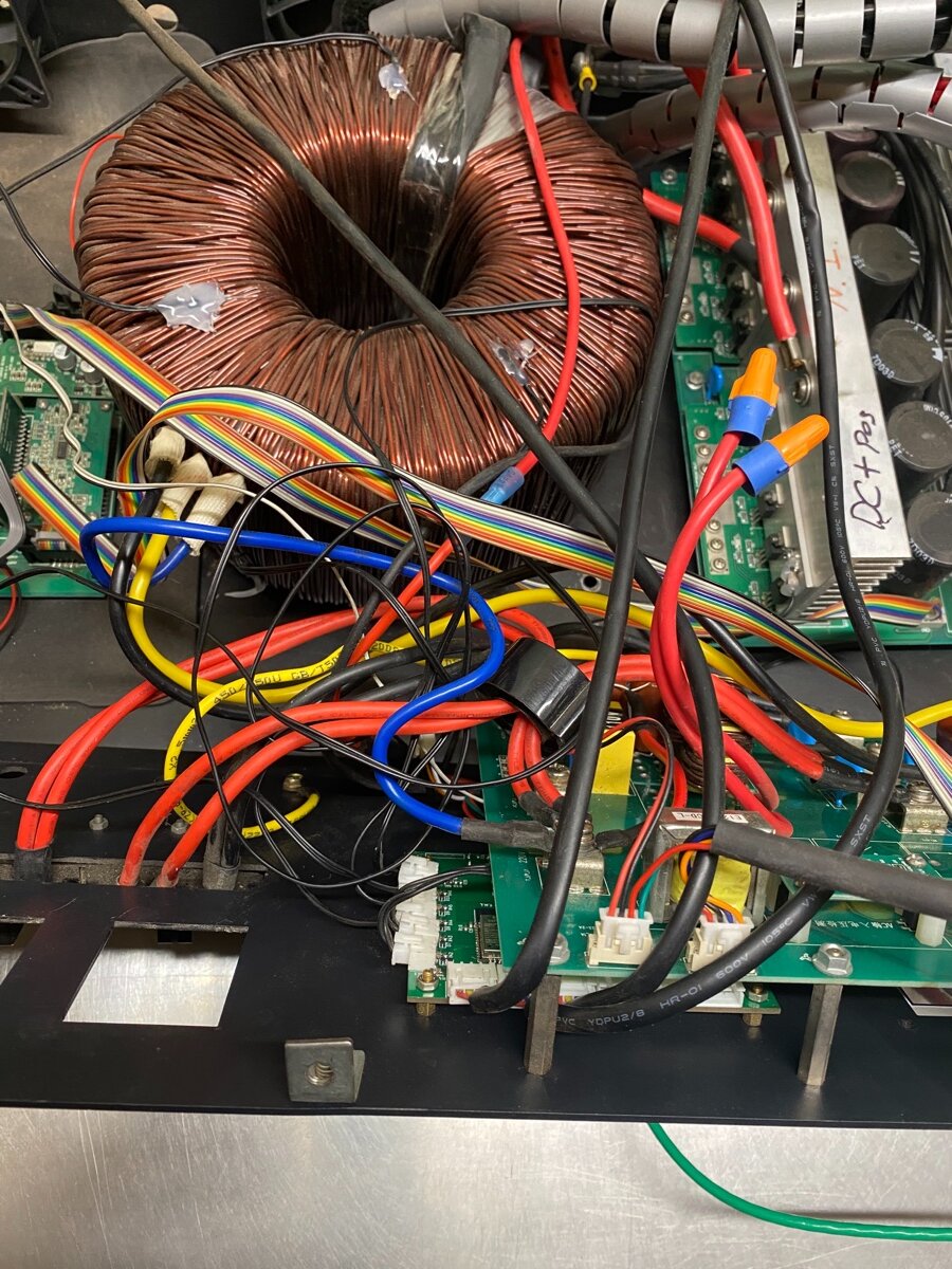
So if I understand correctly I need to plug this one to WiFi bottom connector & reconnect these 2 wires to the hall sensor I depinned?
<a href="/monthly_2021_09/5F37786F-838D-488E-8668-3044595A2459.jpeg.daccf8854f0431850c6cb48fc370977d.jpeg" class="ipsAttachLink ipsAttachLink_image"><img data-fileid="782" src="//forums.genetrysolar.com/applications/core/interface/js/spacer.png" data-src="/monthly_2021_09/5F37786F-838D-488E-8668-3044595A2459.thumb.jpeg.01efadf238a419f266d391ab6c9343d4.jpeg" data-ratio="133.45" width="562" class="ipsImage ipsImage_thumbnailed" alt="5F37786F-838D-488E-8668-3044595A2459.jpeg">
<a href="/monthly_2021_09/2681364D-9293-4C1A-972C-2F0DF35740EF.jpeg.6877df3175c9b47a2ac312193a09157e.jpeg" class="ipsAttachLink ipsAttachLink_image"><img data-fileid="783" src="//forums.genetrysolar.com/applications/core/interface/js/spacer.png" data-src="/monthly_2021_09/2681364D-9293-4C1A-972C-2F0DF35740EF.thumb.jpeg.f6fb64d4ca4d5a00149b5fe5c97c65b4.jpeg" data-ratio="133.45" width="562" class="ipsImage ipsImage_thumbnailed" alt="2681364D-9293-4C1A-972C-2F0DF35740EF.jpeg">
& also have to connect the other 4 pin with the orange/blue/black/white plug back to pj board but only plug the red/black/green/red 4 pin to bottom of WiFi board? Just double checking.
I won’t turn on till it’s confirmed
//content.invisioncic.com/g308908/monthly_2021_09/3C72FCE6-E699-45B7-A8AD-8720C3E9BE9A.thumb.jpeg.245280e43db38e8787869c8d31cbc7ec.jpeg
//content.invisioncic.com/g308908/monthly_2021_09/339D1A1C-EA4A-4F49-A030-56C9BD27FA74.thumb.jpeg.295c7fe6113f81f1b6bae0c804fa463b.jpeg
Last one.
So if I understand correctly I need to plug this one to WiFi bottom connector & reconnect these 2 wires to the hall sensor I depinned?
Correct.
& also have to connect the other 4 pin with the orange/blue/black/white plug back to pj board but only plug the red/black/green/red 4 pin to bottom of WiFi board? Just double checking.
Photos are correct: the orange/blue/black/white does not get connected to anything. Other side with the orange/blue/black/red goes to the output board; photos show everything properly connected.
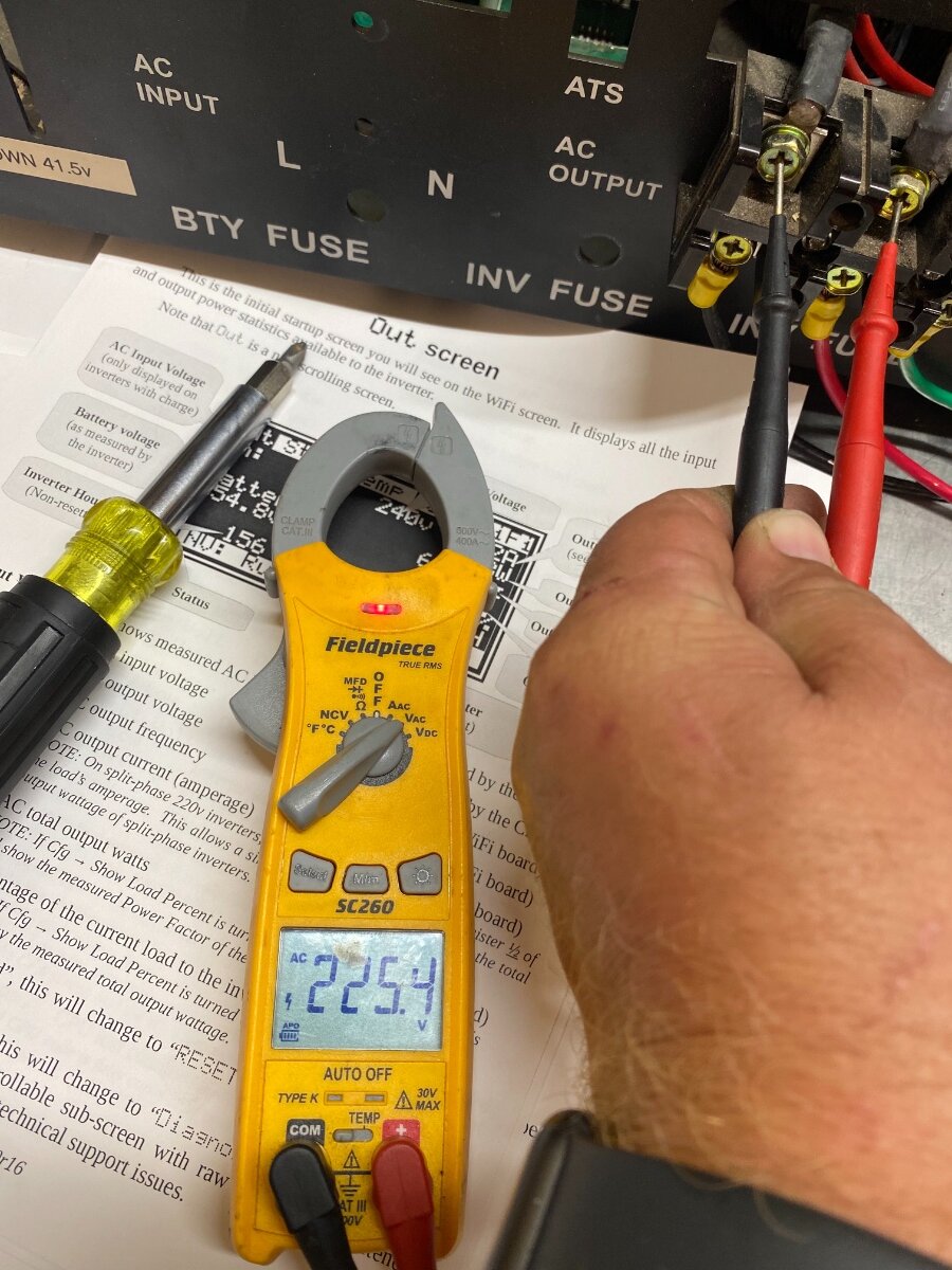
All looks good! Should work properly now.
You may need to calibrate the readings slightly.
And sometime here I need to get the PJ firmware updated a bit...
Just like that magic on a og version 9 PJ. Mind is blown.
This is how we started out...trying to improve a PJ inverter. But due to fundamental design challenges, we ended up making a completely original design for GS inverters. (Completely original ="no stock PJ design.")
Well once I do get everything ready, I’ll be changing out the inverter to y’all’s for sure. I like everything about y’all’s: rhe daisy chain, true output, efficiency, the WiFi board, the list just goes on not to forget the service & support! You guys Rock Sean & Sid.
the list just goes on not to forget the service & support! You guys Rock Sean & Sid.
Just remember that both of us are very human, and highly capable of forgetting/losing track of customers. Until we can afford some CRM software......
Well once I do get everything ready, I’ll be changing out the inverter to y’all’s for sure
The latest youtube video show the 12kw GS will not be available for a while . Do you have the ASL9 transformer in your 15kw PS inverter ? My ASL9 in my 15kw PS overheat and shutdown after 90 minutes running a 4ton heat pump no matter if I use 7 Delta fans. There is something wrong with the core of the ASL9 transformer design from day one by PS engineer . Thank you for your pictures of the GS wifi board and 15kw PS .
Do you have the ASL9 transformer in your 15kw PS inverter ?
It’s the AS9. I need to tape the tags to the case so I don’t lose them